DN9340E/DN9344E
Page
Important Safety Instructions
Page
Declaration of Conformity
Page
Contents
Setup Menu DN9340E
Application Notes
Page
Installation Considerations
Safety Warning
After Unpacking
Page
DN9340E Front Panel
Quick Reference
DN9344E Front Panel
Key Features
DN9340E & DN9344E Key Features
Introducing the DN9340E/DN9344E
Host Software Versions
Space efficiency
Remote control operation
Interface to Midas consoles
Store and Recall Parameters
EQ Access and Displays
Controls, Connectors, Indicators DN9340E
Front Panel DN9340E
Soft keys display
Bypass, Channel Select, Soft Keys and Alphanumeric Display
Selected channel both channels if linked. When a
Soft keys
Touch Strip, Store and Recall, Home Setup and Data Entry
PC Port, Metering and Power
Mains
Rear Panel DN9340E
Inputs a and B
Word clock Input
Signal Flow DN9340E
Signal Flow DN9340E
Operation DN9340E
Operation DN9340E
Home
Home page sub-menus
Touchstrip Operation on the Home
Soft Key Functions
Graphic Equalisation
EQ Flat
Automatic features
Grouping
Touchstrip operation with Graphic equalisation
Parametric Equalisation
EQ remove
Touchstrip operation with Parametric equalisation
Lo Threshold / Level
Dynamic Equalisation
Hi Threshold / Level
Time constants
Touchstrip operation with Dynamic equalisation
Create Filter function
Filters
Filter Type Left Encoder Centre Encoder Right Encoder
Touchstrip operation with Filters
Filter settings
Filter remove
Metering
Clear Down Sequence
Setup Menu DN9340E
Setup Menu DN9340E
To access the Set Up menu pages
General
To switch remote communications off
Remote control via a PC
Comms channel
To select a slave remote communications channel
To select a master remote communications channel
Using a DN9340E for master control
To select a slave communications channel
To remove the unit from the network
To set a Panel Lock
Front Panel lock
To remove the Panel Lock
To change the input source
Analogue/Digital Input Select
To set a Presets lock
Presets lock
Digital Output Clock Select
To select the output clock source
Delay options
LCD contrast adjustment
Naming Pages 7
To enter a name
Ethernet Settings Pages 11
Power-up Logo
Ethernet IP Address
To check and edit the Subnet Mask
Ethernet Subnet Mask Setup
To store settings
Using the DN9340E Memories
To recall settings
Connections
Remote Control
Addresses
Data model
Getting started
Setting the master unit on-line
On a DN9340E
On a DN9344E
Operation
To set up the names
System naming
Copy channel function
To set up the assignment
Solo Tracking operation
Helix DN9340E/DN9344E unit interconnections
Overview
Connecting the Helix DN9340/DN9344E units in a daisy chain
Ethernet Connection
Ethernet connection wireless option
Ethernet connection standard
Configuring the DN9344E for Network Communication
Configuring the DN9340E for Network Communication
Serial Connection Option
Connection and Configuration Procedure
Serial connection details
Alphanumeric displays, SETUP, Metering and Power
Controls, Connectors, Indicators DN9344E
Press to step through the Set Up pages
Power Switch Power on Power on indication Power indication
Indicators
Indicators, Up and Down Buttons, PC Port and Scribble Strips
Mains inlet socket
Rear Panel DN9344E
1B, 2A and 2B
Interface
Signal Flow DN9344E
Signal Flow DN9344E
Operation DN9344E
Operation DN9344E
Remote Comms channels
To select a remote communications channel
To disable remote communications and relay operation
To enable the Contact Closure Relay mode
To set a password
Password
To change the settings for Inputs 1A and 1B
Analogue/Digital Input Select Pages 3
Digital Output Clock Select Pages 5
To change the settings for Output
Subnet Mask
Ethernet Settings
To change the IP address
To change the Subnet Mask
Dynamic EQ
Application Notes
Application Notes
Application Notes
What do we mean by all these Q types?
Constant Q
Proportional Q
Symmetrical Q
What is AES/EBU?
17.1. DN9340E
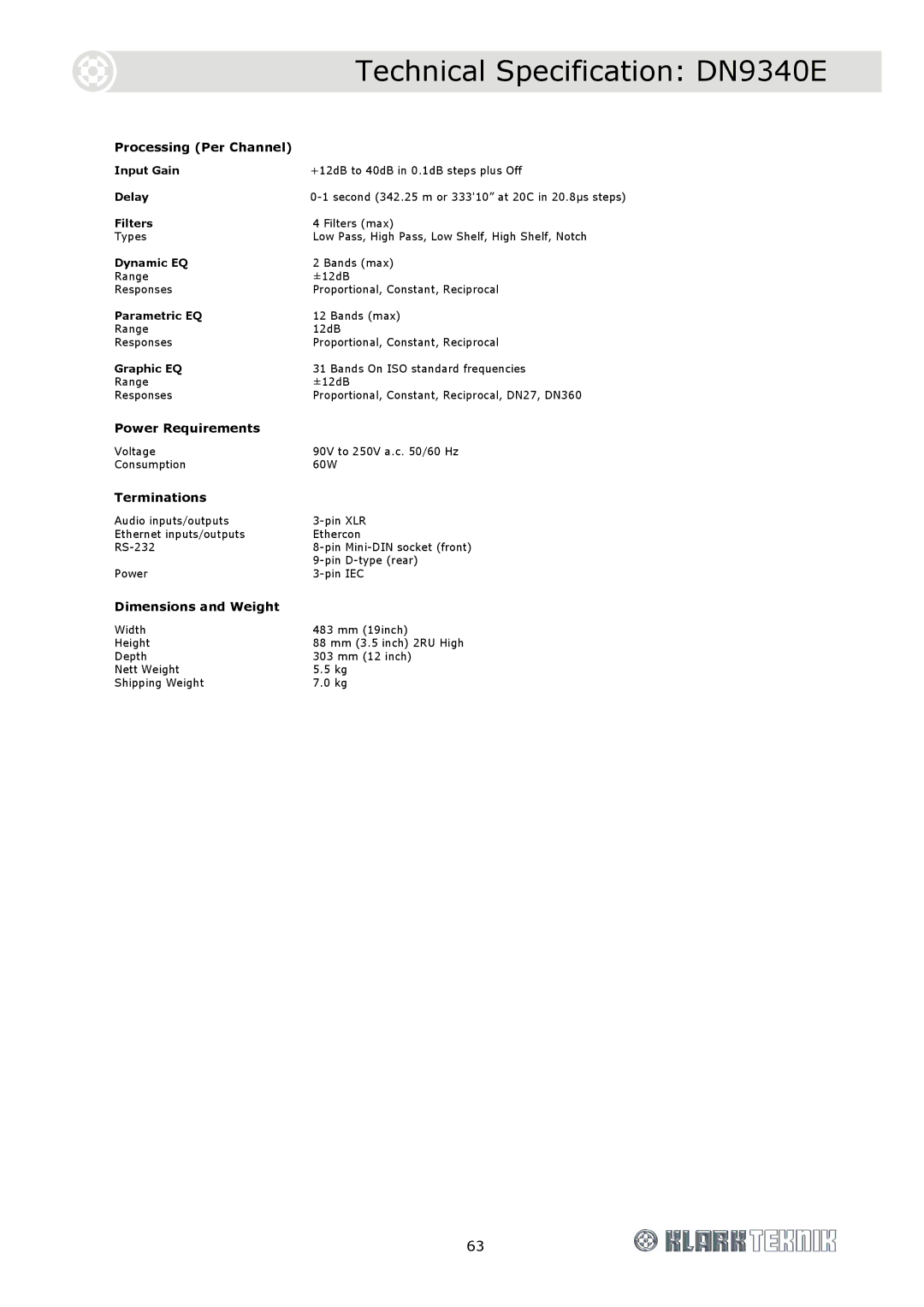
Technical Specification DN9340E
Power Requirements
17.2. DN9344E
Technical Specification DN9344E
Relay Socket Pin D-type rear Power Pin IEC
Battery
Service Information
Replacement