Application Notes
If we now replace the parametric with a Helix equaliser and select the dynamic EQ, we have some additional controls. Frequency and Q controls are as before, but now we have two pairs of controls replacing the single cut and boost control; these are [low threshold] / [low level], and [high threshold] / [high level]. If we set the frequency and Q controls to the area that we wish to control, then the processor will monitor the signal level in that frequency range. If the signal level in this part of the spectrum is below the [low threshold] setting, then the unit considers this a ‘quiet’ signal. The EQ applied to the signal will be controlled by the [low level] control. If the signal level is above the [high threshold] level, then the unit considers this a ‘loud’ signal, and will apply the amount of EQ set by the [high level] control. If the signal level is between the two thresholds, then the equaliser will seamlessly morph between the two equaliser settings in real time. Manual control over attack and release times is available to set the speed of response to suit the application.
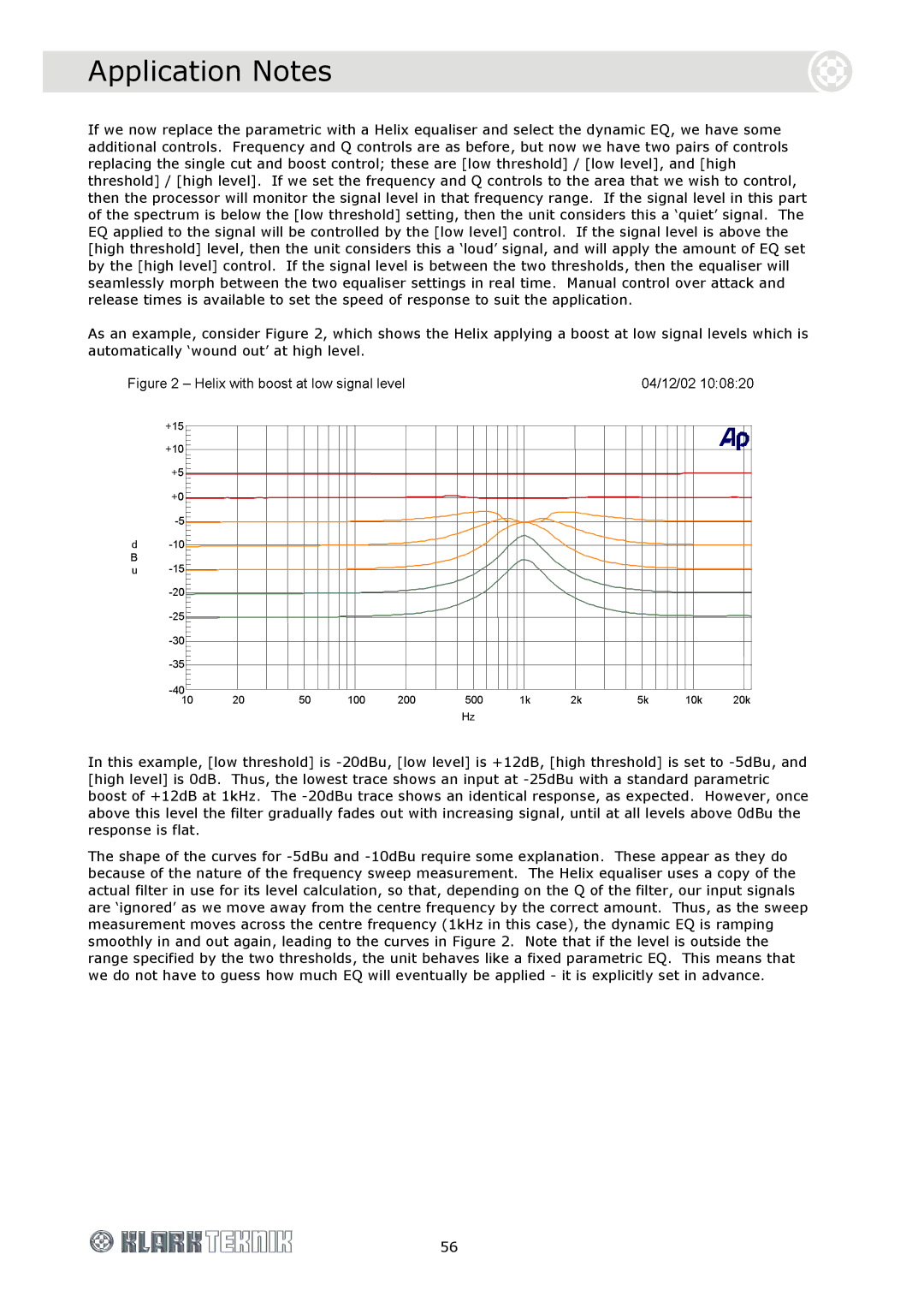
As an example, consider Figure 2, which shows the Helix applying a boost at low signal levels which is automatically ‘wound out’ at high level.
In this example, [low threshold] is
The shape of the curves for
56