Operation: DN9340E
Time constants page
This page allows the attack and release time constants to be set - in other words how quickly the unit will respond to a sudden increase in level (attack) or a sudden decrease in level (release).
EQ settings page
•EQ type - this allows control over the characteristics of the equaliser. Proportional, Constant, and Symmetrical curves are available.
•Graph display - two modes are available, to ensure that clear information is available for any application. “Both” mode shows the overall response of the whole dynamic equaliser. “Active” mode shows just the response of the single section currently being selected for adjustment
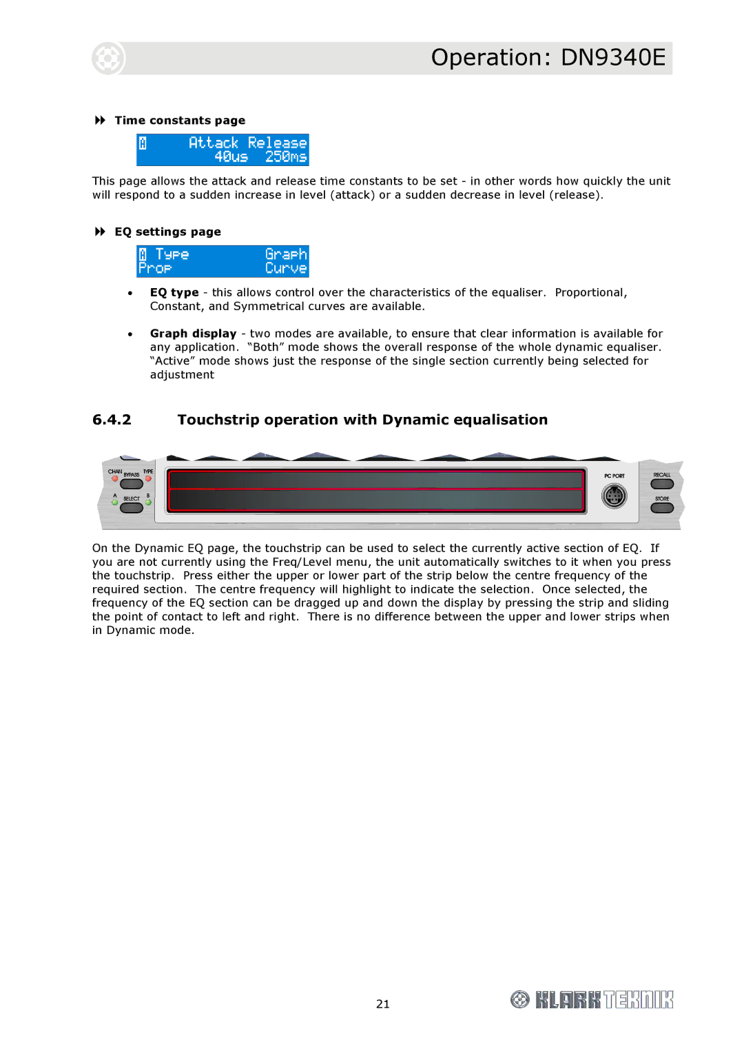
6.4.2Touchstrip operation with Dynamic equalisation
On the Dynamic EQ page, the touchstrip can be used to select the currently active section of EQ. If you are not currently using the Freq/Level menu, the unit automatically switches to it when you press the touchstrip. Press either the upper or lower part of the strip below the centre frequency of the required section. The centre frequency will highlight to indicate the selection. Once selected, the frequency of the EQ section can be dragged up and down the display by pressing the strip and sliding the point of contact to left and right. There is no difference between the upper and lower strips when in Dynamic mode.
21