Operation: DN9340E
6.6. Metering
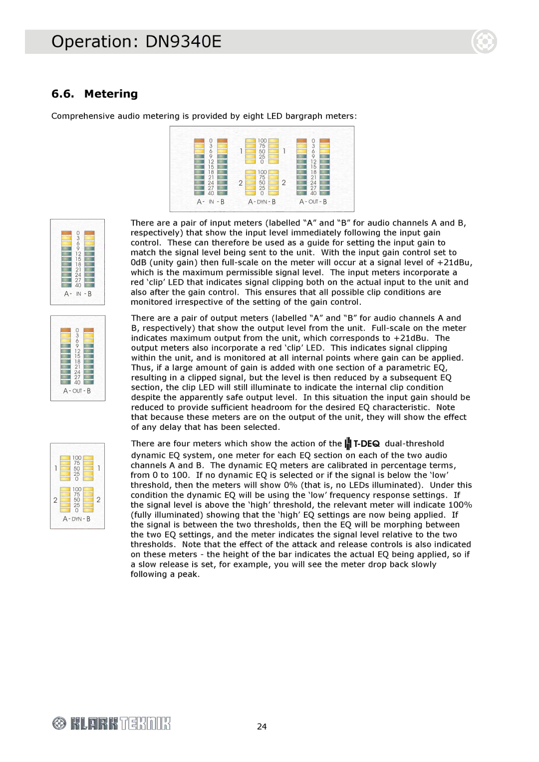
Comprehensive audio metering is provided by eight LED bargraph meters:
There are a pair of input meters (labelled “A” and “B” for audio channels A and B, respectively) that show the input level immediately following the input gain control. These can therefore be used as a guide for setting the input gain to match the signal level being sent to the unit. With the input gain control set to 0dB (unity gain) then
There are a pair of output meters (labelled “A” and “B” for audio channels A and B, respectively) that show the output level from the unit.
There are four meters which show the action of the ![]()
dynamic EQ system, one meter for each EQ section on each of the two audio channels A and B. The dynamic EQ meters are calibrated in percentage terms, from 0 to 100. If no dynamic EQ is selected or if the signal is below the ‘low’ threshold, then the meters will show 0% (that is, no LEDs illuminated). Under this condition the dynamic EQ will be using the ‘low’ frequency response settings. If the signal level is above the ‘high’ threshold, the relevant meter will indicate 100% (fully illuminated) showing that the ‘high’ EQ settings are now being applied. If the signal is between the two thresholds, then the EQ will be morphing between the two EQ settings, and the meter indicates the signal level relative to the two thresholds. Note that the effect of the attack and release controls is also indicated on these meters - the height of the bar indicates the actual EQ being applied, so if a slow release is set, for example, you will see the meter drop back slowly following a peak.
24