0–6D: Clear
This command sets all data to zero in the “Edit Range Start”
–“Edit Range End” region
The “Overwrite.WAV” and “Name” fields in the dialog box are as explained in
0–6E: Copy
This command copies the data from the “Edit Range Start” – “Edit Range End” region
0–6F: Insert
This command inserts the data in the edit buffer (obtained by the “Copy” command) into the waveform at the “Edit Range Start” address. The data that had been at this location will be shifted toward the end of the waveform. (☞p.61 “Sampling mode – Insert/Mix/Paste,” ☞PG p.102
The “From” field in the dialog box lets you select the data that will be inserted. By setting this to RAM, you can insert data that you copied from the specified region in the Sample Edit page. By setting this to DISK, you can insert data that you copied from the specified region in the Disk mode Edit WAVE page.
The “Overwrite.WAV” and “Name” fields in the dialog box are as explained in
0–6G: Mix
This command combines the edit buffer data (obtained by the “Copy” command) with the existing waveform data, beginning at the “Edit Range Start” address. (☞p.61 “Sam- pling mode – Insert/Mix/Paste,” ☞PG p.103
The “Overwrite.WAV” and “Name” fields in the dialog box are as explained in
0–6H: Paste
This command places the edit buffer data (obtained by the “Copy” command) onto the waveform at the “Edit Range Start” address. The data that had been at that location will be replaced by the pasted data. (☞p.61 “Sampling mode – Insert/Mix/Paste,” ☞PG p.103
The “From” field in the dialog box lets you select the data that will be pasted. By setting this to RAM, you can paste data that you copied from the specified region in the Sample Edit page. By setting this to DISK, you can paste data that you copied from the specified region in the Disk mode Edit WAVE page.
The “Overwrite.WAV” and “Name” fields in the dialog box are as explained in
0–6I: Insert Zero
Data with
0–6J: Normalize/Level Adj.
The volume of the data defined by the “Edit Range Start” – “Edit Range End” region will be adjusted uniformly. “Nor- malize” boosts the values of the region to the maximum level that will not cause clipping (distortion). If the level of the sampled data is low, you can use the Normalize function to increase the dynamic range of the sample data. “Level” raises or lowers the level by the amount you specify. This is the same function as the Sampling mode, Sampling P1: Sam- ple Edit page menu command “Normalize/Level Adj.”; here performed on a WAVE file. (For details on the function and procedure, ☞PG p.104
0–6K: Volume Ramp
The data values (volume) of the “Edit Range Start” – “Edit Range End” region will be adjusted to smoothly raise (Fade In) or lower (Fade Out) the volume from “Edit Range Start” to “Edit Range End.” This is the same function as the Sam- pling mode, Sampling P1: Sample Edit page menu com- mand “Volume Ramp”; here performed on a WAVE file. (For details on the function and procedure, ☞PG p.104
The “Overwrite.WAV” and “Name” fields in the dialog box are as explained in
0–6L: Erase Punch Noise
This is the same function as the Sequencer mode, Sequencer P5: Track Edit page menu command “Erase Punch Noise.” (For details on the function and procedure, ☞p.21)
0–6M: Time Stretch (Sustaining)
This is the same function as the Sequencer mode, Sequencer P5: Track Edit page menu command “Time Stretch.” (For details on the function and procedure, ☞p.22)
0–6N: Transfer WAVE to Track
This is the same function as the Sequencer mode, Sequencer P5: Track Edit page menu command “Transfer WAVE.” (For details on the function and procedure, ☞p.23)
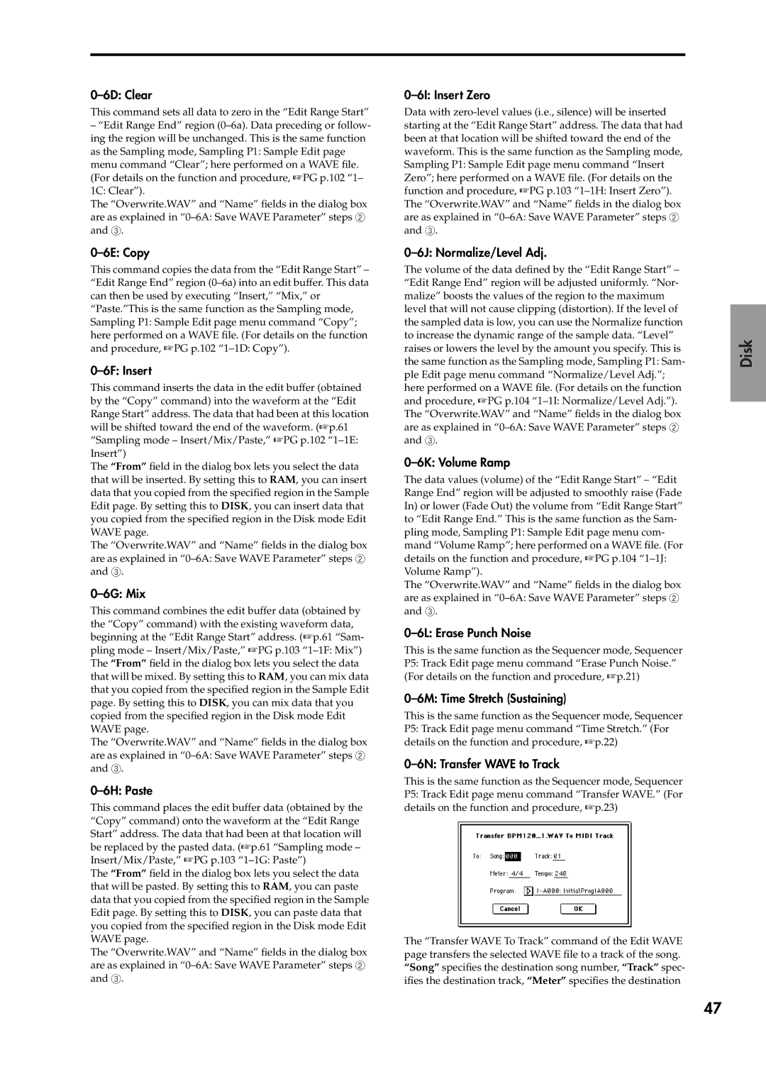
The “Transfer WAVE To Track” command of the Edit WAVE page transfers the selected WAVE file to a track of the song. “Song” specifies the destination song number, “Track” spec- ifies the destination track, “Meter” specifies the destination
Disk
Global
Other functionality Program Combination Sampling
47
