Operation
External Maintenance Bypass Switch Configurations
The External Maintenance Bypass Switch has three configuration options:
•External maintenance bypass installed with interlock option
•External maintenance bypass installed without interlock option
•Not installed
Table 4 | External maintenance switch configuration options | |||
|
|
| ||
External |
|
| ||
Maintenance Switch | Option Auxiliary Contact |
| ||
Options | Status | User Prompt | ||
|
| open = On Test position or | Prompts the user to rotate to On Line position, | |
|
| Maintenance position, or jumper | ||
Installed with | Just before retransfer. | |||
removed | ||||
Interlock Option |
|
| ||
closed = On “ON LINE” position | Manual or automatic start (one button) is | |||
|
| |||
|
| (default jumper) | allowed all the way to load being | |
|
|
|
| |
|
| open = jumper removed | Prompts the user to install jumper just before | |
|
| retransfer” | ||
Not installed |
| |||
closed = default jumper | Manual or automatic start (one button) is | |||
|
| |||
|
| allowed all the way to load being | ||
|
|
| ||
|
|
|
| |
|
| Open = Jumper removed | Prompts the user to install jumper just before | |
Installed without | retransfer” | |||
| ||||
interlock option |
|
| ||
Closed = default jumper | Prompts the user to verify the switch is in on- | |||
|
| line position before a retransfer is allowed | ||
|
|
| ||
Regardless of how the configuration is set, if the auxiliary contacts are open, the user is unable to issue a retransfer command through the manual transfer / retransfer screen.
If the option is installed and the auxiliary contact status is read as switch is in the Bypass or Mainte- nance position, the “critical load shutdown” message reads “UPS off”.
Multiple Battery Cabinets
The Npower system offers an option allowing for the installation of more than two battery cabinets. The option consists of a Multiple Battery Breaker (MBB) board that mounts on the control door and an Input Contact Isolator (ICI) board that mounts in the option area (See the Multiple Battery Breaker Option in the options manual.)
The ICI board allows the Npower system to sense multiple battery cabinets, and the MBB board allows the UPS to support multiple battery cabinets by supplying power to the UVR coil of additional battery cabinets.
To access the screen for setting the number of battery cabinets in the system, navigate from the MAIN MENU to CONFIGURATION to SYSTEM SETTINGS, page 3. Select NUMBER OF BAT- TERY CABINETS to bring up the following
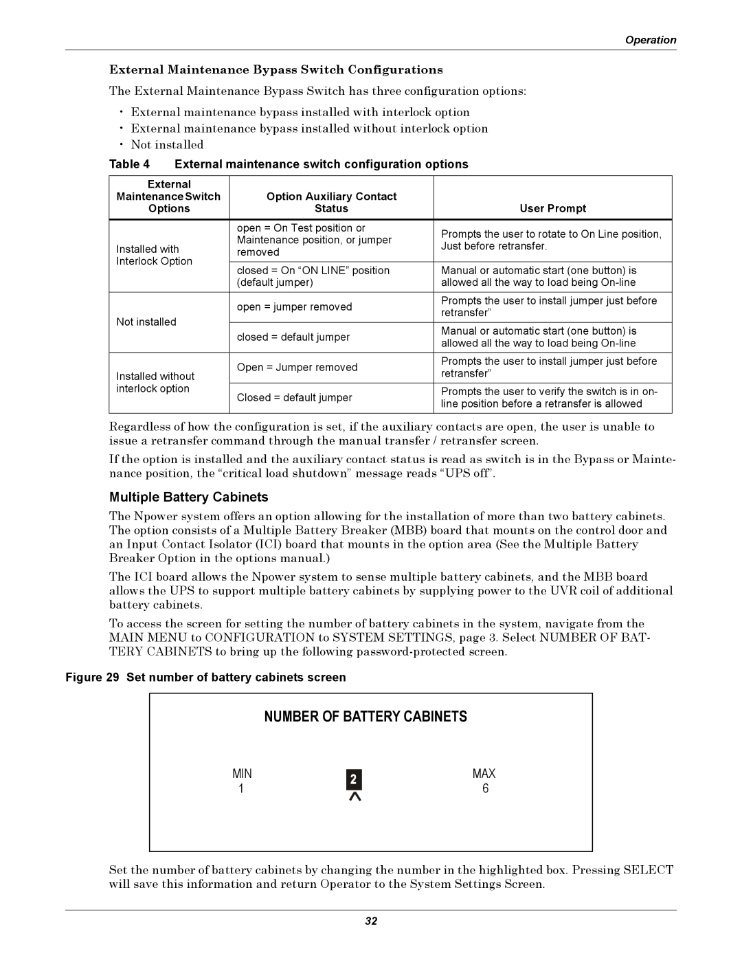
Figure 29 Set number of battery cabinets screen
NUMBER OF BATTERY CABINETS
MIN 1
MAX 6
Set the number of battery cabinets by changing the number in the highlighted box. Pressing SELECT will save this information and return Operator to the System Settings Screen.
32