Operation
The second page is the STATUS, which includes:
•Static Bypass Switch Line (Open/Closed)
•Static Bypass Switch Load (Open/Closed)
•Input Contactor (Open/Closed)
•Output Contactor (Open/Closed)
•Trap Filter (On/Off) (If installed)
•Int. MBP (Normal/Bypass Service)
•Ext. MBP (Open/Closed)
•Battery CB (Open/Closed)
•SBS (On/Off)
•Rectifier (On/Off)
•Inverter (On/Off)
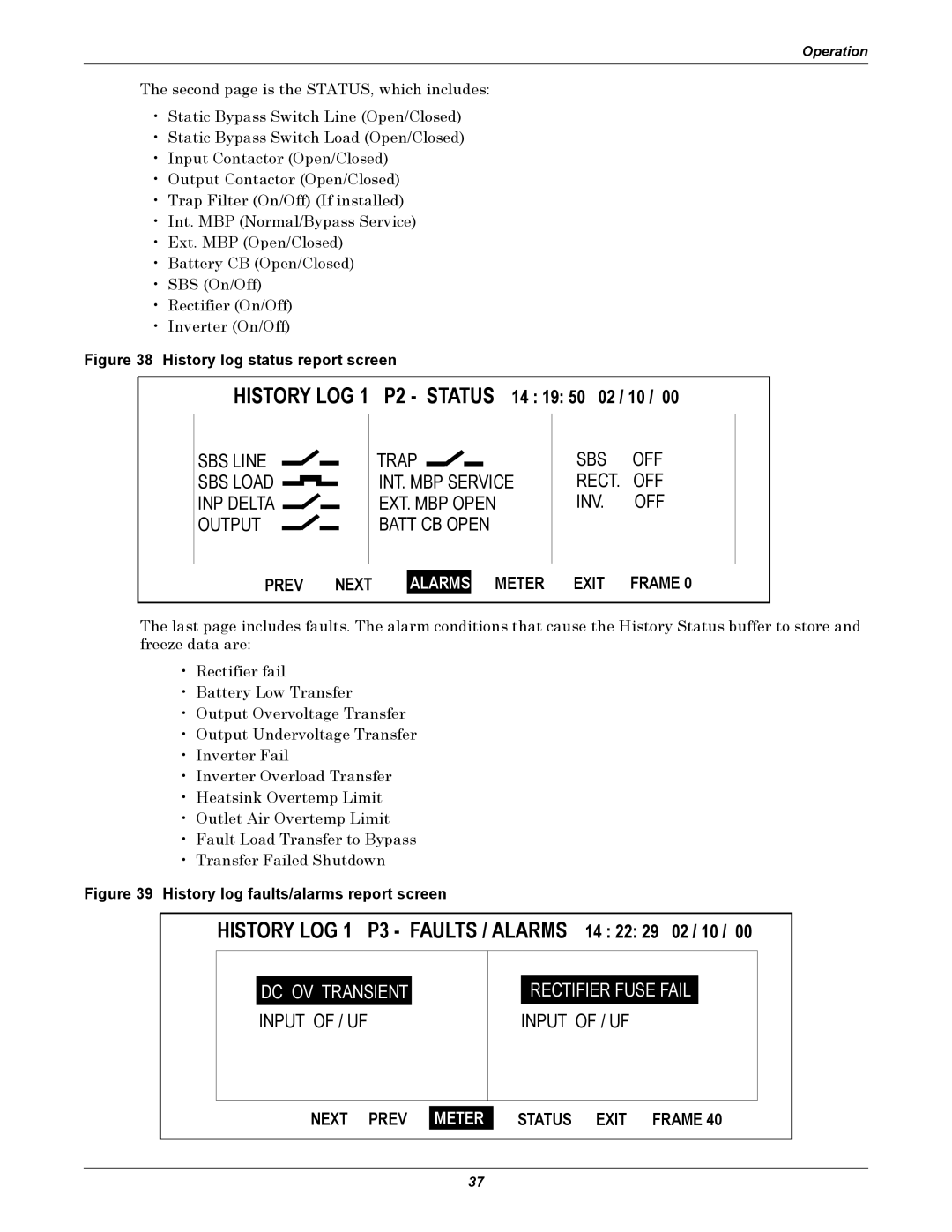
Figure 38 History log status report screen
HISTORY LOG 1 P2 - STATUS 14 : 19: 50 02 / 10 / 00
SBS LINE |
|
|
|
|
|
|
|
|
|
| TRAP |
|
|
|
| |
|
|
|
|
|
|
|
|
|
|
|
|
|
| |||
SBS LOAD |
|
|
|
|
|
|
| INT. MBP SERVICE | ||||||||
INP DELTA | EXT. MBP OPEN | |||||||||||||||
OUTPUT |
|
|
|
|
|
| BATT CB OPEN | |||||||||
|
|
|
|
|
|
|
|
|
|
| ||||||
|
|
|
|
|
|
|
|
|
|
|
|
|
|
|
|
|
SBS OFF RECT. OFF INV. OFF
PREV NEXT
ALARMS
METER EXIT FRAME 0
The last page includes faults. The alarm conditions that cause the History Status buffer to store and freeze data are:
•Rectifier fail
•Battery Low Transfer
•Output Overvoltage Transfer
•Output Undervoltage Transfer
•Inverter Fail
•Inverter Overload Transfer
•Heatsink Overtemp Limit
•Outlet Air Overtemp Limit
•Fault Load Transfer to Bypass
•Transfer Failed Shutdown
Figure 39 History log faults/alarms report screen
HISTORY LOG 1 P3 - FAULTS / ALARMS 14 : 22: 29 02 / 10 / 00
DC OV TRANSIENT
INPUT OF / UF
RECTIFIER FUSE FAIL
INPUT OF / UF
NEXT PREV
METER
STATUS EXIT FRAME 40
37