Operation
The Output/Load status screen displays the following
•Output AC Volts AB, BC, CA
•Output AC Volts AN, BN, CN
•Output Current A, B, C
•Output kVA, kW, A, B, C
•Output Frequency
•% rated kVA and kW
•Overload Condition (with timer in seconds)
5.SYSTEM STATUS. When the SYSTEM STATUS box on the Mimic Display Screen (Figure 14) shows a flashing FAULTS AND ALARMS message, highlight it and press SELECT. This displays information about faults and alarms. Fault messages are displayed in reverse video (highlighted - light on dark) while alarm messages are displayed in regular video (dark on light). Alarm messages activate the audible alarm until the ALARM SILENCE button is pressed. To clear a latching alarm, you must also press the ALARM RESET button after the alarm condition is corrected.
Faults and Alarms
The Npower is designed to alert the Operator to system conditions that warrant careful monitoring and/or corrective action. A fault is an undesirable system condition that can cause further damage to the system or potentially drop the load if not acted upon. An alarm indicates an abnormal system con- dition significant enough to warrant being annunciated and logged. During normal operation no alarm messages should be present.
Figure 19 Active faults and alarms screen
ACTIVE FAULTS AND ALARMS
USER SHUTDOWN
EXIT | 03:58:29 05/22/00 |
If input power is lost, the following screen will be displayed:
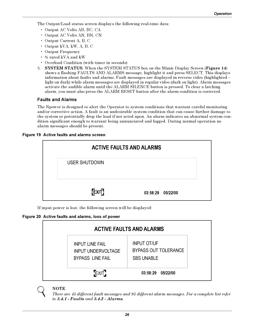
Figure 20 Active faults and alarms, loss of power
ACTIVE FAULTS AND ALARMS
INPUT LINE FAIL INPUT UNDERVOLTAGE BYPASS LINE FAIL
INPUT OT/UF
BYPASS OUT TOLERANCE SBS UNABLE
EXIT |
03:58:29 05/22/00
NOTE
There are 45 different fault messages and 95 different alarm messages. For a complete list refer to 3.4.1 - Faults and 3.4.2 - Alarms.
26