Operation
3.5.5Setting Up External Communication Devices
All external communication devices, including the modem, are optional equipment. Connections to communication ports are made by wiring cables to terminal boards. Connection points are shown on the Control Wiring Interconnect Diagram in the Installation Manual. Contact Liebert Global Services for assistance when attaching an external device to your UPS system.
Any terminal that accepts the standard
Data link requirements are:
•Asynchronous
•Terminals may be configured as DTE or DCE
•Baud Rate:
Modem 1200 or 2400
Terminal 9600 only
•Data Bits: 8
•Stop Bits: 1
•Parity: None
•Handshaking: Not required
•Full Duplex
3.6Modes Of Operation
This section illustrates the flow of power through circuit breakers, switches, and UPS components dur- ing various modes of operation. The same modes of operation apply to all configurations of the Liebert Npower UPS. Highlighted (thick) lines in the diagrams indicate power flow and power availability.
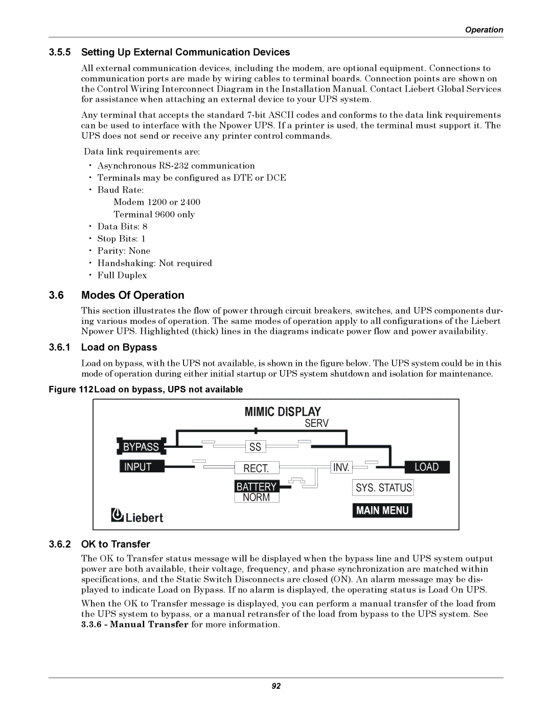
3.6.1Load on Bypass
Load on bypass, with the UPS not available, is shown in the figure below. The UPS system could be in this mode of operation during either initial startup or UPS system shutdown and isolation for maintenance.
Figure 112Load on bypass, UPS not available
MIMIC DISPLAY
SERV
SS
RECT. ![]()
![]()
![]()
![]() INV.
INV. ![]()
![]()
![]()
![]() LOAD
LOAD
|
|
|
|
|
|
|
|
|
|
|
|
|
|
|
BATTERY |
|
|
|
|
|
|
|
|
|
|
|
| SYS. STATUS | |
NORM |
|
|
|
|
|
|
|
|
|
|
|
|
|
|
|
|
| ||||||||||||
|
|
|
|
|
|
|
|
|
|
|
|
|
|
|
|
|
|
|
|
|
|
|
|
|
|
|
|
|
|
3.6.2OK to Transfer
The OK to Transfer status message will be displayed when the bypass line and UPS system output power are both available, their voltage, frequency, and phase synchronization are matched within specifications, and the Static Switch Disconnects are closed (ON). An alarm message may be dis- played to indicate Load on Bypass. If no alarm is displayed, the operating status is Load On UPS.
When the OK to Transfer message is displayed, you can perform a manual transfer of the load from the UPS system to bypass, or a manual retransfer of the load from bypass to the UPS system. See 3.3.6 - Manual Transfer for more information.
92