Operation
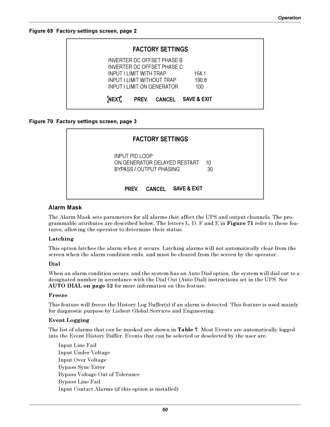
Figure 69 Factory settings screen, page 2
|
|
| FACTORY SETTINGS | |
INVERTER DC OFFSET PHASE B |
| |||
INVERTER DC OFFSET PHASE C |
| |||
INPUT I LIMIT WITH TRAP | 164.1 | |||
INPUT I LIMIT WITHOUT TRAP | 190.8 | |||
INPUT I LIMIT ON GENERATOR | 100 | |||
| NEXTNEXT PREV. CANCEL | SAVE & EXIT | ||
| ||||
|
|
|
|
|
Figure 70 Factory settings screen, page 3
FACTORY SETTINGS
INPUT PID LOOP |
|
ON GENERATOR DELAYED RESTART | 10 |
BYPASS / OUTPUT PHASING | 30 |
PREV. CANCEL SAVE & EXIT
Alarm Mask
The Alarm Mask sets parameters for all alarms that affect the UPS and output channels. The pro- grammable attributes are described below. The letters L, D, F and E in Figure 71 refer to these fea- tures, allowing the operator to determine their status.
Latching
This option latches the alarm when it occurs. Latching alarms will not automatically clear from the screen when the alarm condition ends, and must be cleared from the screen by the operator.
Dial
When an alarm condition occurs, and the system has an Auto Dial option, the system will dial out to a designated number in accordance with the Dial Out (Auto Dial) instructions set in the UPS. See AUTO DIAL on page 52 for more information on this feature.
Freeze
This feature will freeze the History Log Buffer(s) if an alarm is detected. This feature is used mainly for diagnostic purpose by Liebert Global Services and Engineering.
Event Logging
The list of alarms that can be masked are shown in Table 7. Most Events are automatically logged into the Event History Buffer. Events that can be selected or deselected by the user are:
Input Line Fail Input Under Voltage Input Over Voltage Bypass Sync Error
Bypass Voltage Out of Tolerance Bypass Line Fail
Input Contact Alarms (if this option is installed)
50