Operation
3.3.2Startup
There are two start up scenarios which can be followed depending on whether there is already power supplied to the UPS and the UPS is on Bypass, or there is no power to the UPS. Follow the appropri- ate instructions.
First Scenario
Power is not supplied to the UPS (Upstream breakers are open). Locate the Rotary Switch located on the inside of the cabinet on the lower right side as you face the cabinet. Turn the Rotary Switch to the Normal position. For a Single Input unit close the upstream breaker so that power is applied to the UPS. For Dual Input units close both the Input and Bypass line breakers so that power is applied to the Input of the UPS and the Bypass line. At this time, power will be applied to the load through the internal static bypass.
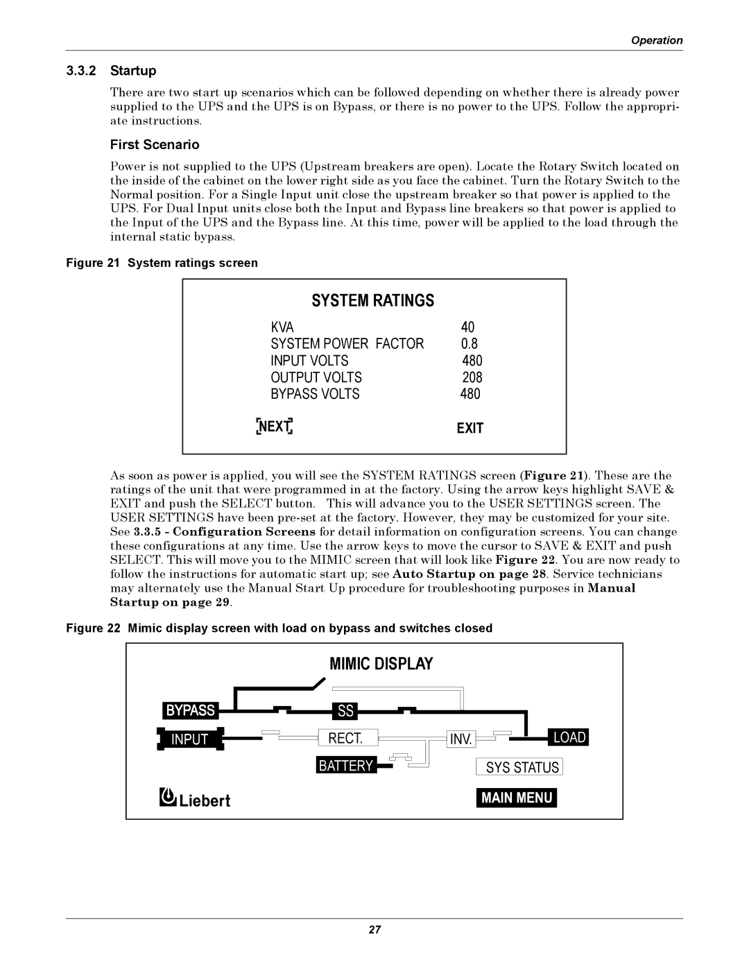
Figure 21 System ratings screen
SYSTEM RATINGS
KVA | 40 |
SYSTEM POWER FACTOR | 0.8 |
INPUT VOLTS | 480 |
OUTPUT VOLTS | 208 |
BYPASS VOLTS | 480 |
NEXT | EXIT |
As soon as power is applied, you will see the SYSTEM RATINGS screen (Figure 21). These are the ratings of the unit that were programmed in at the factory. Using the arrow keys highlight SAVE & EXIT and push the SELECT button. This will advance you to the USER SETTINGS screen. The USER SETTINGS have been
Figure 22 Mimic display screen with load on bypass and switches closed
MIMIC DISPLAY
|
|
|
|
|
|
|
|
|
|
|
|
|
|
|
|
|
|
|
|
|
|
|
|
|
|
|
|
|
|
|
|
|
|
|
|
|
|
|
|
|
|
|
|
|
|
|
|
|
|
|
|
|
|
|
|
|
|
|
|
|
|
|
|
|
|
|
|
|
|
|
|
|
|
|
|
|
|
|
|
|
|
|
|
|
|
|
|
|
|
|
|
|
|
|
|
|
|
|
|
|
|
|
|
|
|
|
|
|
|
|
|
|
|
|
|
|
|
|
|
|
|
|
|
|
|
|
|
|
|
|
|
|
|
|
|
|
|
|
|
|
|
|
|
|
|
|
|
|
|
|
|
|
|
|
|
|
|
|
|
|
|
|
|
|
|
|
|
|
|
|
|
|
|
|
|
|
|
|
|
|
|
|
|
|
|
|
|
|
|
|
|
|
|
|
|
|
|
|
|
|
|
|
|
|
|
|
|
|
|
|
|
|
|
|
|
|
|
|
|
|
|
|
|
|
|
|
| RECT. |
|
|
|
|
|
|
|
|
|
|
|
|
|
|
|
| INV. |
|
|
|
|
| LOAD |
| |||||
|
|
|
|
|
|
|
|
|
|
|
|
| BATTERY |
|
|
|
|
|
|
|
|
|
|
|
|
|
|
|
|
|
|
|
|
|
|
|
|
|
| |||
|
|
|
|
|
|
|
|
|
|
|
|
|
|
|
|
|
|
|
|
|
|
|
|
|
|
|
|
|
|
|
|
|
|
|
|
| ||||||
|
|
|
|
|
|
|
|
|
|
|
|
|
|
|
|
|
|
|
|
|
|
|
|
|
|
|
|
|
|
| SYS STATUS | |||||||||||
|
|
|
|
|
|
|
|
|
|
|
|
|
|
|
|
|
|
|
|
|
|
|
|
|
|
|
|
|
|
|
|
|
|
|
|
|
|
|
|
|
|
|
|
|
|
|
|
|
|
|
|
|
|
|
|
|
|
|
|
|
|
|
|
|
|
|
|
|
|
|
|
|
|
|
|
|
|
|
|
|
|
|
|
|
|
27