Operation
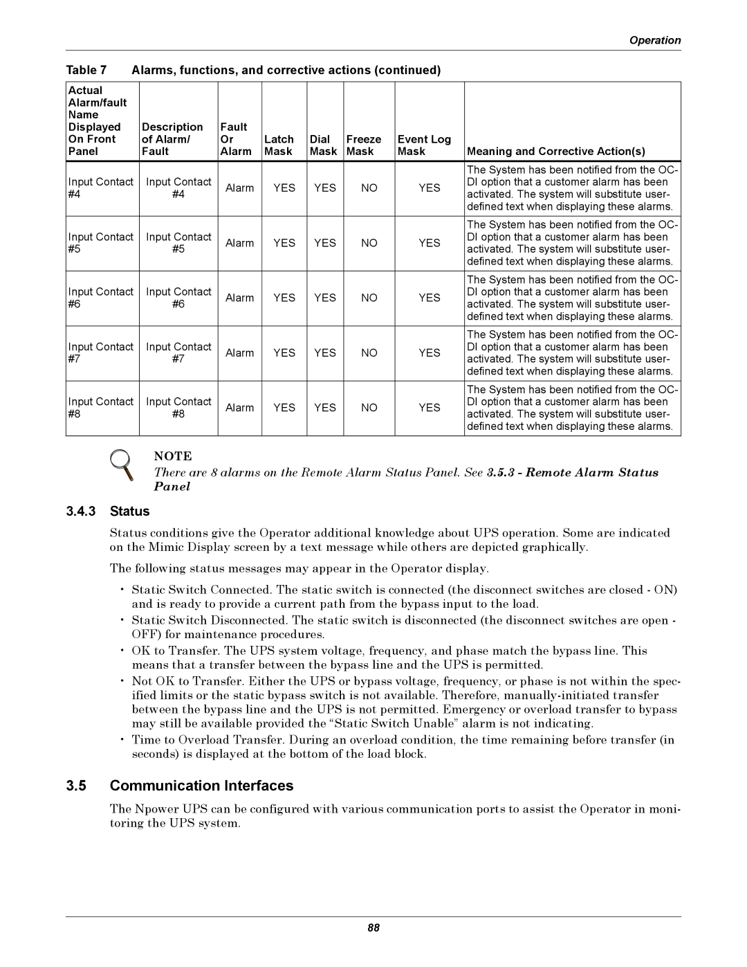
Table 7 | Alarms, functions, and corrective actions (continued) |
| ||||||
|
|
|
|
|
|
|
|
|
Actual |
|
|
|
|
|
|
|
|
Alarm/fault |
|
|
|
|
|
|
|
|
Name |
|
|
|
|
|
|
|
|
Displayed |
| Description | Fault |
|
|
|
|
|
On Front |
| of Alarm/ | Or | Latch | Dial | Freeze | Event Log |
|
Panel |
| Fault | Alarm | Mask | Mask | Mask | Mask | Meaning and Corrective Action(s) |
|
|
|
|
|
|
|
| The System has been notified from the OC- |
Input Contact | Input Contact | Alarm | YES | YES | NO | YES | DI option that a customer alarm has been | |
#4 |
| #4 | activated. The system will substitute user- | |||||
|
|
|
|
|
| |||
|
|
|
|
|
|
|
| defined text when displaying these alarms. |
|
|
|
|
|
|
|
|
|
|
|
|
|
|
|
|
| The System has been notified from the OC- |
Input Contact | Input Contact | Alarm | YES | YES | NO | YES | DI option that a customer alarm has been | |
#5 |
| #5 | activated. The system will substitute user- | |||||
|
|
|
|
|
| |||
|
|
|
|
|
|
|
| defined text when displaying these alarms. |
|
|
|
|
|
|
|
|
|
|
|
|
|
|
|
|
| The System has been notified from the OC- |
Input Contact | Input Contact | Alarm | YES | YES | NO | YES | DI option that a customer alarm has been | |
#6 |
| #6 | activated. The system will substitute user- | |||||
|
|
|
|
|
| |||
|
|
|
|
|
|
|
| defined text when displaying these alarms. |
|
|
|
|
|
|
|
|
|
|
|
|
|
|
|
|
| The System has been notified from the OC- |
Input Contact | Input Contact | Alarm | YES | YES | NO | YES | DI option that a customer alarm has been | |
#7 |
| #7 | activated. The system will substitute user- | |||||
|
|
|
|
|
| |||
|
|
|
|
|
|
|
| defined text when displaying these alarms. |
|
|
|
|
|
|
|
|
|
|
|
|
|
|
|
|
| The System has been notified from the OC- |
Input Contact | Input Contact | Alarm | YES | YES | NO | YES | DI option that a customer alarm has been | |
#8 |
| #8 | activated. The system will substitute user- | |||||
|
|
|
|
|
| |||
|
|
|
|
|
|
|
| defined text when displaying these alarms. |
|
|
|
|
|
|
|
|
|
NOTE
There are 8 alarms on the Remote Alarm Status Panel. See 3.5.3 - Remote Alarm Status
Panel
3.4.3Status
Status conditions give the Operator additional knowledge about UPS operation. Some are indicated on the Mimic Display screen by a text message while others are depicted graphically.
The following status messages may appear in the Operator display.
•Static Switch Connected. The static switch is connected (the disconnect switches are closed - ON) and is ready to provide a current path from the bypass input to the load.
•Static Switch Disconnected. The static switch is disconnected (the disconnect switches are open - OFF) for maintenance procedures.
•OK to Transfer. The UPS system voltage, frequency, and phase match the bypass line. This means that a transfer between the bypass line and the UPS is permitted.
•Not OK to Transfer. Either the UPS or bypass voltage, frequency, or phase is not within the spec- ified limits or the static bypass switch is not available. Therefore,
•Time to Overload Transfer. During an overload condition, the time remaining before transfer (in seconds) is displayed at the bottom of the load block.
3.5Communication Interfaces
The Npower UPS can be configured with various communication ports to assist the Operator in moni- toring the UPS system.
88