Operation
The following faults are detected by the UPS controls. Corrective actions, where possible, are auto- matic.
•Active Filter Fail
•Battery Overtemp CB Trip
•Battery Ground Fault CB Trip
•Bypass Power Supply Fail
•EPO Shutdown
•Heatsink Overtemp Limit
•Input Power Supply Fail
•Output Power Supply Fail
•Outlet Air Overtemp Limit
•Power Supply F1 Fail
•SWGR Power Fail
•DC Undervoltage Steady State
•DC Overvoltage Steady State
•Rectifier Fail
•Inverter Fail
•Overtemp Time out Shutdown
•Fault Transfer Failed - Shutdown
•Controller Fault
•Hardware Shutdown.
•MM Control Power Fail.
•MM Memory Fail.
•Option Power Supply Fail
3.4.2Alarms
An alarm is an indication of an abnormal system condition significant enough to warrant being annunciated and logged. Alarm conditions may indicate that a UPS system parameter is out of its normal operating range, or may signal an external problem. In some cases an alarm may trigger a corrective action. Many alarm conditions will return to normal in due time and the alarm itself will no longer be “active.”
Summary Alarm
The Npower system features a Summary Alarm, which captures the presence of individual faults and alarms. This alarm may be assigned to any PRB relay. See Customer Alarm Interface on page 52.
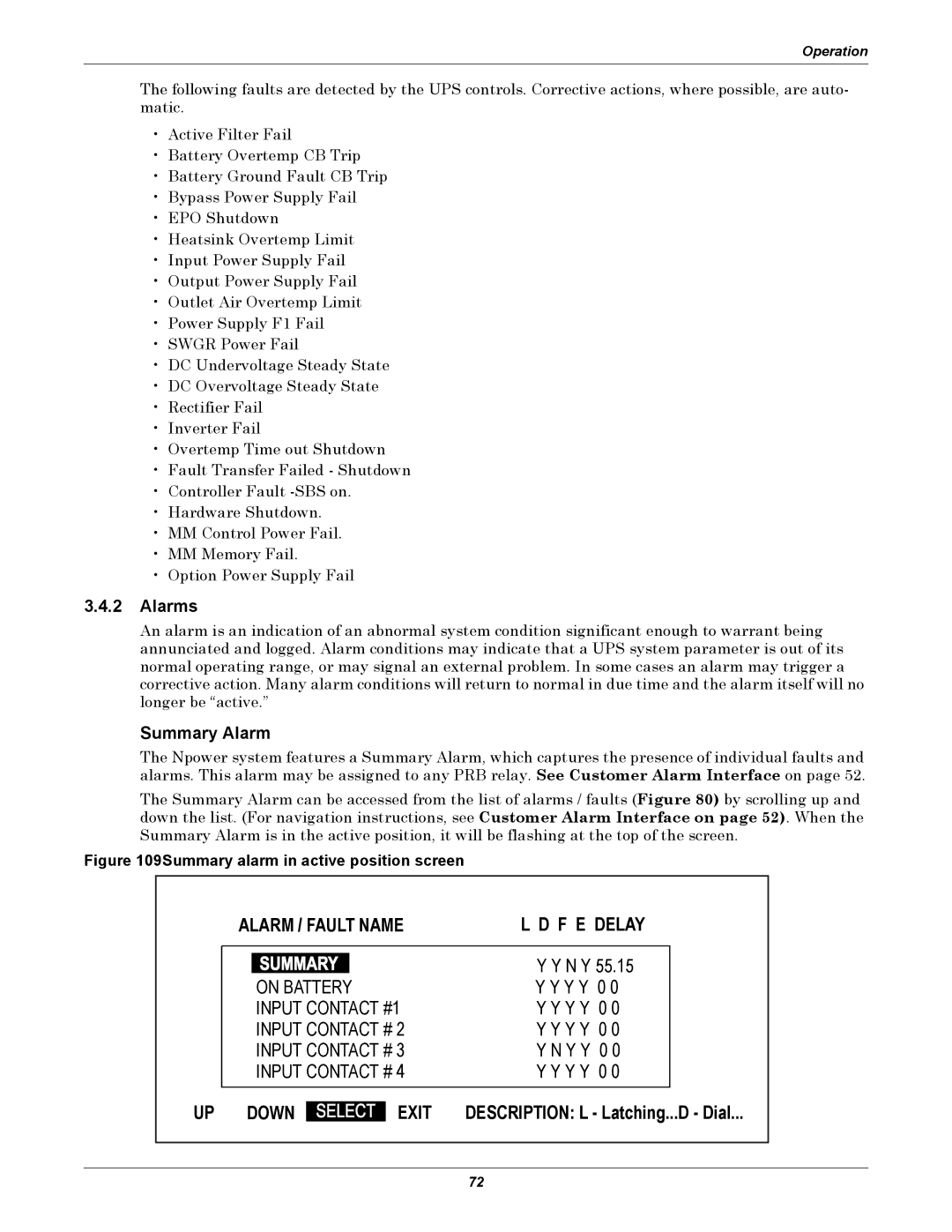
The Summary Alarm can be accessed from the list of alarms / faults (Figure 80) by scrolling up and down the list. (For navigation instructions, see Customer Alarm Interface on page 52). When the Summary Alarm is in the active position, it will be flashing at the top of the screen.
Figure 109Summary alarm in active position screen
ALARM / FAULT NAME | L D F E DELAY |
ON BATTERY
INPUT CONTACT #1
INPUT CONTACT # 2
INPUT CONTACT # 3
INPUT CONTACT # 4
UP DOWN | EXIT |
Y Y N Y 55.15
Y Y Y Y 0 0
Y Y Y Y 0 0
Y Y Y Y 0 0
Y N Y Y 0 0
Y Y Y Y 0 0
DESCRIPTION: L - Latching...D - Dial...
72