Operation
Navigating Protocol
For the screen above and others like it, the normal screen navigation rules are changed. It is impor- tant to differentiate between the selections at the bottom of the display screen (UP/DOWN/ADD/ REMOVE/CLEAR/EXIT) and the navigation buttons or arrow keys below the display screen. To scroll up the Alarm/Fault list, use the arrow keys to highlight the UP selection at the bottom of the display screen. Next, press the SELECT navigation button. Continue this sequence until you have positioned the proper Alarm/Fault in the active position at the top of the list. To scroll down the list, use the arrow key to highlight the DOWN selection at the bottom of the display screen. Next, press the SELECT navigation. Continue until the proper alarm is positioned at the top of the list.
When the selected Alarm/Fault is in the active position at the top of the list, it will be flashing. To attach this alarm to a Programmable Relay, use the arrow keys to highlight ADD at the bottom of the display screen. Press SELECT and your selection will now appear in the right hand box.
You may attach up to four alarms to each relay by following this procedure. Since there are almost 200 alarms, it is advised that you review the entire list and note which alarms you want connected to each relay before beginning your selections. Keep in mind that if you attach more than 1 alarm to the relay, and the relay is triggered, you will not be advised which of the alarms is activated. You may be able to determine this through other diagnostic features of the Npower, but it will not be evident from this feature.
If you decide to remove an alarm from the selected alarm set, scroll the list to put the alarm you want to remove in the top (flashing) position on the ALARM/FAULT NAME list. Use the arrow keys to move the cursor to REMOVE. Press SELECT to remove the alarm from the right hand (connected) list.
If you wish to clear all the alarms and start over, move the cursor to CLEAR and press SELECT.
After you have selected the alarms you want connected to PROG RELAY #1 use the arrow keys to move the cursor to EXIT, press SELECT. This will put you back to the PROGRAMMABLE OUTPUT RELAY BOARD # 1 screen. Follow the procedure above to program the next relay. When all of the relays you wish to program have been completed, highlight SAVE & EXIT and press SELECT.
! CAUTION
You must select save & exit from the programmable output relay board screen or your selections will not be saved.
If you have a second relay board installed, from the CUSTOMER ALARM INTERFACE screen, repeat the same procedures for RELAY BOARD # 2.
3.3.6Manual Transfer
The Manual Transfer screen allows the Operator to transfer the critical load to and from bypass through the static bypass switch. This screen can only be accessed when the rotary switch is on Nor- mal position. To access the screen, start at the MAIN MENU. Highlight MANUAL TRANSFER and press SELECT. There are 3 status options for the Inverter: In sync, lag x degrees, and lead x degrees.
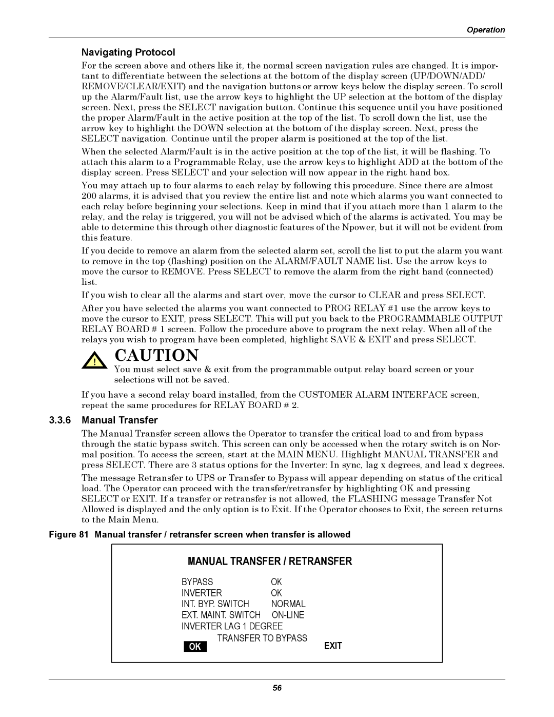
The message Retransfer to UPS or Transfer to Bypass will appear depending on status of the critical load. The Operator can proceed with the transfer/retransfer by highlighting OK and pressing SELECT or EXIT. If a transfer or retransfer is not allowed, the FLASHING message Transfer Not Allowed is displayed and the only option is to Exit. If the Operator chooses to Exit, the screen returns to the Main Menu.
Figure 81 Manual transfer / retransfer screen when transfer is allowed
MANUAL TRANSFER / RETRANSFER
BYPASS | OK |
| ||
INVERTER | OK |
| ||
INT. BYP. SWITCH | NORMAL |
| ||
EXT. MAINT. SWITCH |
| |||
INVERTER LAG 1 DEGREE |
| |||
|
| TRANSFER TO BYPASS | EXIT | |
| OK | |||
|
|
| ||
56