Operation
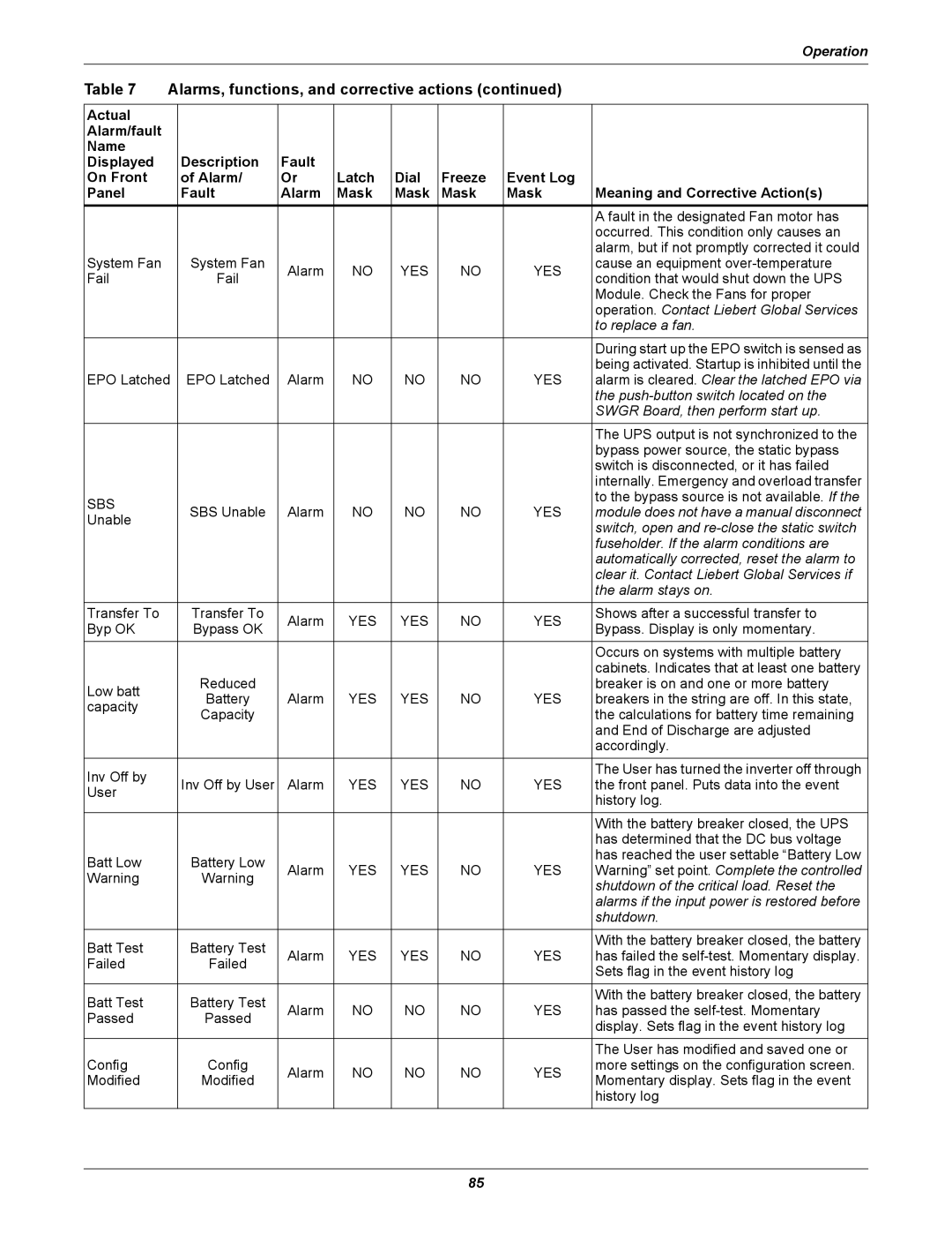
Table 7 | Alarms, functions, and corrective actions (continued) |
| ||||||
|
|
|
|
|
|
|
|
|
Actual |
|
|
|
|
|
|
|
|
Alarm/fault |
|
|
|
|
|
|
|
|
Name |
|
|
|
|
|
|
|
|
Displayed |
| Description | Fault |
|
|
|
|
|
On Front |
| of Alarm/ | Or | Latch | Dial | Freeze | Event Log |
|
Panel |
| Fault | Alarm | Mask | Mask | Mask | Mask | Meaning and Corrective Action(s) |
|
|
|
|
|
|
|
| A fault in the designated Fan motor has |
|
|
|
|
|
|
|
| occurred. This condition only causes an |
|
|
|
|
|
|
|
| alarm, but if not promptly corrected it could |
System Fan |
| System Fan | Alarm | NO | YES | NO | YES | cause an equipment |
Fail |
| Fail | condition that would shut down the UPS | |||||
|
|
|
|
|
| |||
|
|
|
|
|
|
|
| Module. Check the Fans for proper |
|
|
|
|
|
|
|
| operation. Contact Liebert Global Services |
|
|
|
|
|
|
|
| to replace a fan. |
|
|
|
|
|
|
|
| During start up the EPO switch is sensed as |
|
|
|
|
|
|
|
| being activated. Startup is inhibited until the |
EPO Latched | EPO Latched | Alarm | NO | NO | NO | YES | alarm is cleared. Clear the latched EPO via | |
|
|
|
|
|
|
|
| the |
|
|
|
|
|
|
|
| SWGR Board, then perform start up. |
|
|
|
|
|
|
|
| The UPS output is not synchronized to the |
|
|
|
|
|
|
|
| bypass power source, the static bypass |
|
|
|
|
|
|
|
| switch is disconnected, or it has failed |
|
|
|
|
|
|
|
| internally. Emergency and overload transfer |
SBS |
| SBS Unable | Alarm | NO | NO | NO | YES | to the bypass source is not available. If the |
| module does not have a manual disconnect | |||||||
Unable |
| |||||||
|
|
|
|
|
|
| switch, open and | |
|
|
|
|
|
|
|
| |
|
|
|
|
|
|
|
| fuseholder. If the alarm conditions are |
|
|
|
|
|
|
|
| automatically corrected, reset the alarm to |
|
|
|
|
|
|
|
| clear it. Contact Liebert Global Services if |
|
|
|
|
|
|
|
| the alarm stays on. |
Transfer To |
| Transfer To | Alarm | YES | YES | NO | YES | Shows after a successful transfer to |
Byp OK |
| Bypass OK | Bypass. Display is only momentary. | |||||
|
|
|
|
|
| |||
|
|
|
|
|
|
|
| Occurs on systems with multiple battery |
|
|
|
|
|
|
|
| cabinets. Indicates that at least one battery |
Low batt |
| Reduced |
|
|
|
|
| breaker is on and one or more battery |
| Battery | Alarm | YES | YES | NO | YES | breakers in the string are off. In this state, | |
capacity |
| |||||||
| Capacity |
|
|
|
|
| the calculations for battery time remaining | |
|
|
|
|
|
|
| ||
|
|
|
|
|
|
|
| and End of Discharge are adjusted |
|
|
|
|
|
|
|
| accordingly. |
Inv Off by |
|
|
|
|
|
|
| The User has turned the inverter off through |
| Inv Off by User | Alarm | YES | YES | NO | YES | the front panel. Puts data into the event | |
User |
| |||||||
|
|
|
|
|
|
| history log. | |
|
|
|
|
|
|
|
| |
|
|
|
|
|
|
|
|
|
|
|
|
|
|
|
|
| With the battery breaker closed, the UPS |
|
|
|
|
|
|
|
| has determined that the DC bus voltage |
Batt Low |
| Battery Low |
|
|
|
|
| has reached the user settable “Battery Low |
| Alarm | YES | YES | NO | YES | Warning” set point. Complete the controlled | ||
Warning |
| Warning | ||||||
|
|
|
|
|
| shutdown of the critical load. Reset the | ||
|
|
|
|
|
|
|
| |
|
|
|
|
|
|
|
| alarms if the input power is restored before |
|
|
|
|
|
|
|
| shutdown. |
Batt Test |
| Battery Test |
|
|
|
|
| With the battery breaker closed, the battery |
| Alarm | YES | YES | NO | YES | has failed the | ||
Failed |
| Failed | ||||||
|
|
|
|
|
| Sets flag in the event history log | ||
|
|
|
|
|
|
|
| |
|
|
|
|
|
|
|
|
|
Batt Test |
| Battery Test |
|
|
|
|
| With the battery breaker closed, the battery |
| Alarm | NO | NO | NO | YES | has passed the | ||
Passed |
| Passed | ||||||
|
|
|
|
|
| display. Sets flag in the event history log | ||
|
|
|
|
|
|
|
| |
|
|
|
|
|
|
|
|
|
|
|
|
|
|
|
|
| The User has modified and saved one or |
Config |
| Config | Alarm | NO | NO | NO | YES | more settings on the configuration screen. |
Modified |
| Modified | Momentary display. Sets flag in the event | |||||
|
|
|
|
|
| |||
|
|
|
|
|
|
|
| history log |
|
|
|
|
|
|
|
|
|
85