Product Description
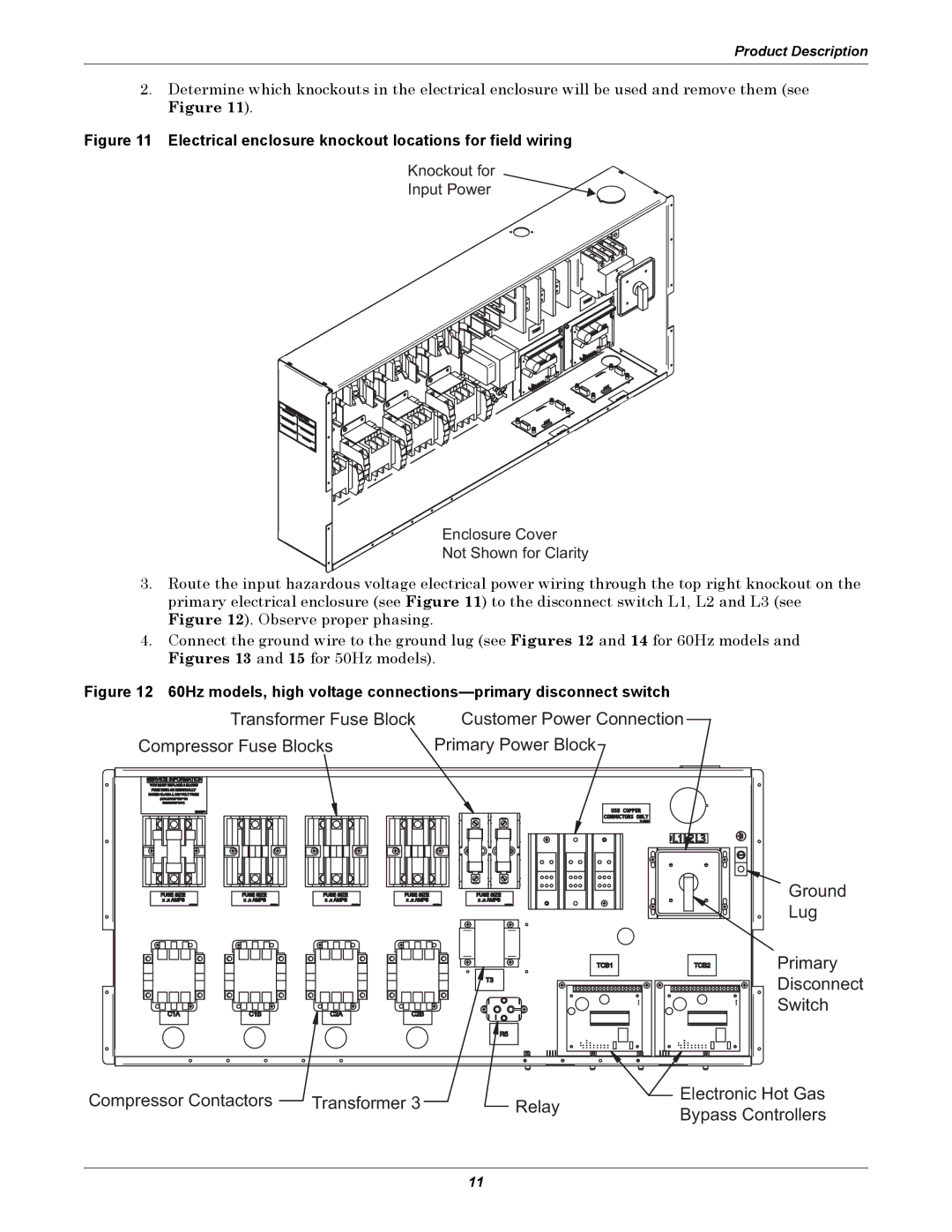
2.Determine which knockouts in the electrical enclosure will be used and remove them (see Figure 11).
Figure 11 Electrical enclosure knockout locations for field wiring
Knockout for
Input Power
Enclosure Cover
Not Shown for Clarity
3.Route the input hazardous voltage electrical power wiring through the top right knockout on the primary electrical enclosure (see Figure 11) to the disconnect switch L1, L2 and L3 (see Figure 12). Observe proper phasing.
4.Connect the ground wire to the ground lug (see Figures 12 and 14 for 60Hz models and Figures 13 and 15 for 50Hz models).
Figure 12 60Hz models, high voltage connections—primary disconnect switch
Transformer Fuse Block | Customer Power Connection |
Compressor Fuse Blocks | Primary Power Block |
|
|
Ground
Lug
Primary
Disconnect
Switch
Compressor Contactors | Transformer 3 | Relay | Electronic Hot Gas | |
Bypass Controllers | ||||
|
|
|
11