Product Description
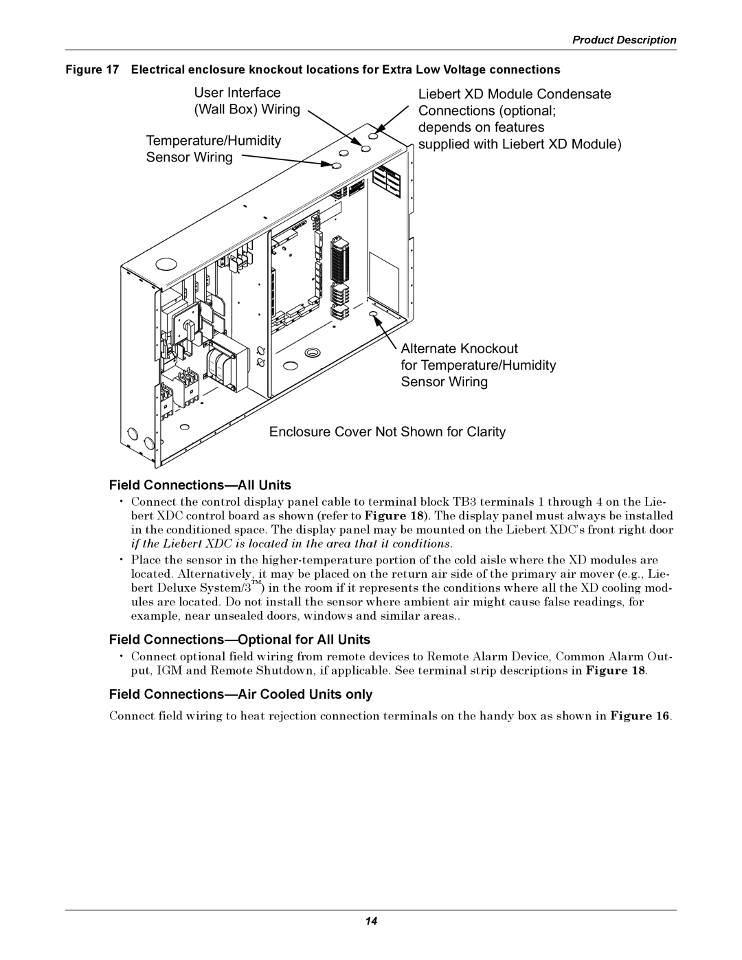
Figure 17 Electrical enclosure knockout locations for Extra Low Voltage connections
User Interface
(Wall Box) Wiring
Temperature/Humidity Sensor Wiring ![]()
Liebert XD Module Condensate Connections (optional; depends on features
supplied with Liebert XD Module)
![]() Alternate Knockout
Alternate Knockout
for Temperature/Humidity
Sensor Wiring
Enclosure Cover Not Shown for Clarity
Field Connections—All Units
•Connect the control display panel cable to terminal block TB3 terminals 1 through 4 on the Lie- bert XDC control board as shown (refer to Figure 18). The display panel must always be installed in the conditioned space. The display panel may be mounted on the Liebert XDC’s front right door if the Liebert XDC is located in the area that it conditions.
•Place the sensor in the
Field Connections—Optional for All Units
•Connect optional field wiring from remote devices to Remote Alarm Device, Common Alarm Out- put, IGM and Remote Shutdown, if applicable. See terminal strip descriptions in Figure 18.
Field Connections—Air Cooled Units only
Connect field wiring to heat rejection connection terminals on the handy box as shown in Figure 16.
14