Piping and Filling with Refrigerant:
Bypass Flow Controllers
To ensure the Liebert XDC pumps operate within the optimum range, some installations require one or more bypass flow controller(s). These devices are added to the field piping, and simulate the flow of additional cooling modules.
Each bypass flow controller should be installed with one shutoff valve to allow the controller to be dis- abled when cooling modules are added to a Liebert XD system.
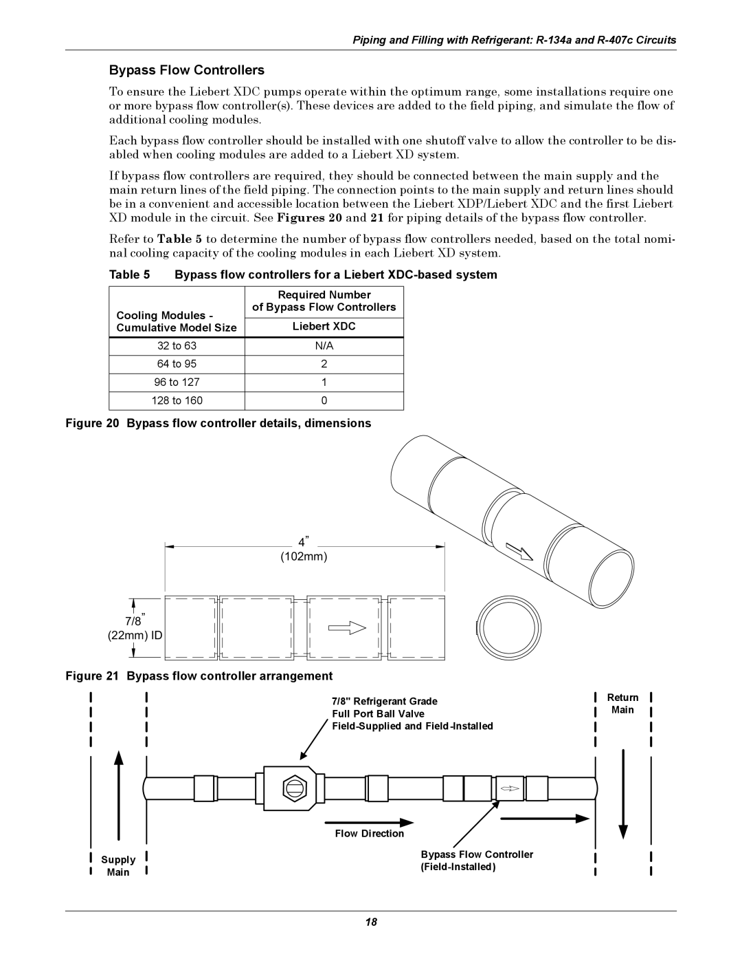
If bypass flow controllers are required, they should be connected between the main supply and the main return lines of the field piping. The connection points to the main supply and return lines should be in a convenient and accessible location between the Liebert XDP/Liebert XDC and the first Liebert XD module in the circuit. See Figures 20 and 21 for piping details of the bypass flow controller.
Refer to Table 5 to determine the number of bypass flow controllers needed, based on the total nomi- nal cooling capacity of the cooling modules in each Liebert XD system.
Table 5 Bypass flow controllers for a Liebert XDC-based system
| Required Number | |
Cooling Modules - | of Bypass Flow Controllers | |
| ||
Liebert XDC | ||
Cumulative Model Size | ||
|
| |
32 to 63 | N/A | |
|
| |
64 to 95 | 2 | |
|
| |
96 to 127 | 1 | |
|
| |
128 to 160 | 0 | |
|
|
Figure 20 Bypass flow controller details, dimensions
4”
(102mm)
7/8”
(22mm) ID
Figure 21 Bypass flow controller arrangement
| 7/8" Refrigerant Grade |
|
|
|
|
| Return | ||||||||
|
|
|
|
|
| Main | |||||||||
| Full Port Ball Valve |
|
|
|
|
| |||||||||
|
|
|
|
|
|
|
| ||||||||
|
|
|
|
|
|
|
|
|
|
|
|
|
|
|
|
|
|
|
|
|
|
|
|
|
|
|
|
|
|
|
|
|
|
|
|
|
|
|
|
|
|
|
|
|
|
|
|
|
|
|
|
|
|
|
|
|
|
|
|
|
|
|
|
|
|
|
|
|
|
|
|
|
|
|
|
|
|
|
|
|
|
|
|
|
|
|
|
|
|
|
|
|
|
|
|
|
|
|
|
|
|
|
|
|
|
|
|
|
|
|
|
| Flow Direction | |
Supply | Bypass Flow Controller | |
Main | ||
|
18