Piping and Filling with Refrigerant:
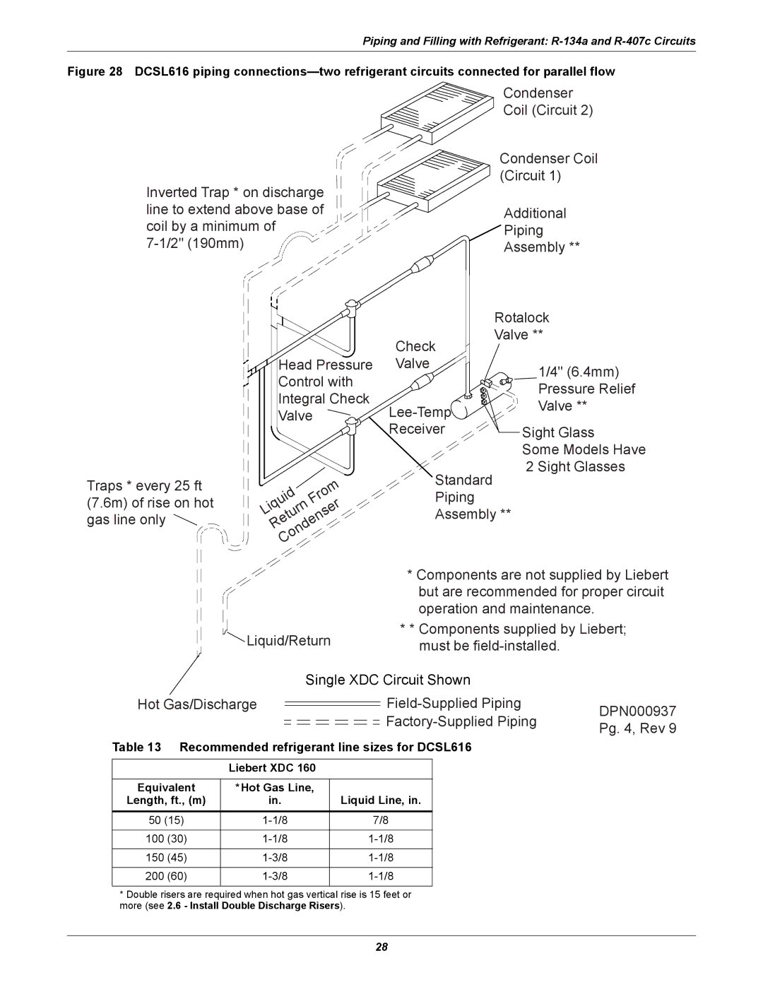
Figure 28 DCSL616 piping connections—two refrigerant circuits connected for parallel flow
Inverted Trap * on discharge line to extend above base of coil by a minimum of
Condenser Coil (Circuit 2)
Condenser Coil (Circuit 1)
Additional Piping Assembly **
Traps * every 25 ft (7.6m) of rise on hot gas line only
Head Pressure Control with Integral Check Valve
|
|
|
|
|
|
|
| m | |
|
|
| d |
| o |
| |||
|
|
|
| r |
| ||||
|
| i |
|
|
|
| |||
| u |
|
| F |
| r | |||
q |
|
| n |
|
| ||||
i |
|
|
|
| e | ||||
L |
|
|
| r |
|
| |||
|
| u |
| s | |||||
|
| t |
|
| n |
| |||
|
| e |
|
| e |
|
| ||
R |
|
| d |
|
|
| |||
|
|
|
| n |
|
|
| ||
|
|
| o |
|
|
|
| ||
|
| C |
|
|
|
|
|
| |
| Rotalock |
Check | Valve ** |
| |
Valve | 1/4" (6.4mm) |
| |
| Pressure Relief |
Valve ** | |
| |
Receiver | Sight Glass |
| Some Models Have |
2 Sight Glasses
Standard
Piping Assembly **
* Components are not supplied by Liebert
|
|
| but are recommended for proper circuit | ||
|
|
| operation and maintenance. |
| |
| Liquid/Return | * * Components supplied by Liebert; | |||
| must be |
| |||
|
|
|
| ||
| Single XDC Circuit Shown |
| |||
Hot Gas/Discharge | DPN000937 | ||||
|
|
| |||
|
|
| Pg. 4, Rev 9 | ||
|
|
|
|
| |
Table 13 Recommended refrigerant line sizes for DCSL616 |
| ||||
|
|
|
|
|
|
| Liebert XDC 160 |
|
|
| |
|
|
|
|
|
|
Equivalent | *Hot Gas Line, |
|
|
|
|
Length, ft., (m) | in. |
| Liquid Line, in. |
|
|
50 (15) |
| 7/8 |
|
| |
|
|
|
|
|
|
100 (30) |
|
|
| ||
|
|
|
|
|
|
150 (45) |
|
|
| ||
|
|
|
|
|
|
200 (60) |
|
|
| ||
|
|
|
|
|
|
*Double risers are required when hot gas vertical rise is 15 feet or more (see 2.6 - Install Double Discharge Risers).
28
