Piping and Filling with Refrigerant:
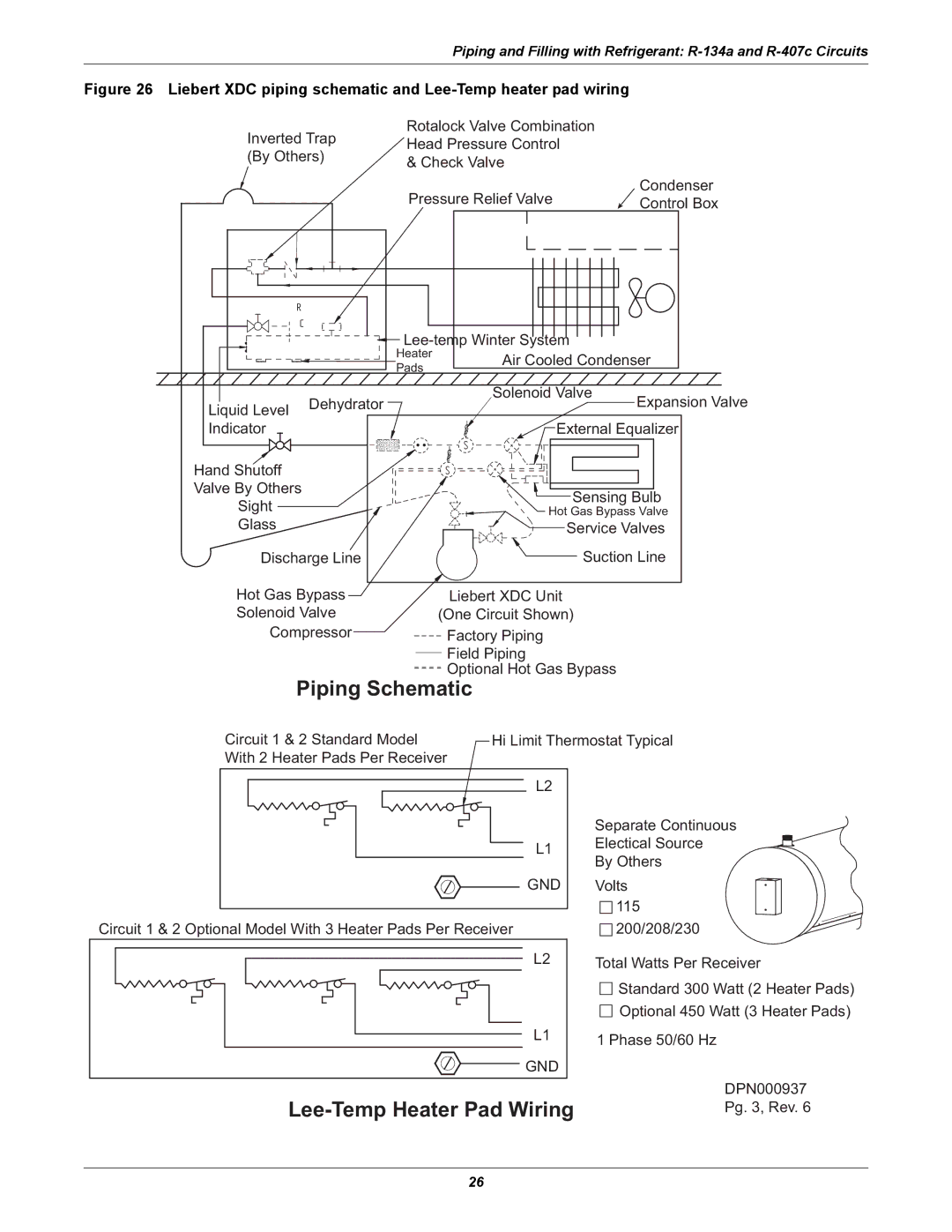
Figure 26 Liebert XDC piping schematic and Lee-Temp heater pad wiring
Rotalock Valve Combination
Inverted Trap | Head Pressure Control |
| ||
(By Others) |
| |||
& Check Valve |
| |||
|
|
|
| |
|
|
| Pressure Relief Valve | Condenser |
|
|
| Control Box | |
|
|
| ||
|
|
| ||
|
| Heater | Air Cooled Condenser | |
|
| Pads | ||
|
|
|
| |
Liquid Level | Dehydrator |
| Solenoid Valve | Expansion Valve |
|
| |||
|
|
|
| |
Indicator |
|
| External Equalizer | |
Hand Shutoff |
|
|
|
|
Valve By Others |
|
| Sensing Bulb | |
Sight |
|
| ||
|
| Hot Gas Bypass Valve | ||
Glass |
|
| Service Valves | |
Discharge Line |
| Suction Line | ||
Hot Gas Bypass | Liebert XDC Unit |
|
Solenoid Valve | (One Circuit Shown) |
|
Compressor | Factory Piping |
|
| Field Piping |
|
| Optional Hot Gas Bypass | |
Piping Schematic |
| |
Circuit 1 & 2 Standard Model | Hi Limit Thermostat Typical | |
With 2 Heater Pads Per Receiver |
| |
| L2 |
|
|
| Separate Continuous |
| L1 | Electical Source |
| By Others | |
|
| |
| GND | Volts |
|
| 115 |
Circuit 1 & 2 Optional Model With 3 Heater Pads Per Receiver | 200/208/230 | |
| L2 | Total Watts Per Receiver |
|
| Standard 300 Watt (2 Heater Pads) |
|
| Optional 450 Watt (3 Heater Pads) |
| L1 | 1 Phase 50/60 Hz |
| GND |
|
| DPN000937 | |
Pg. 3, Rev. 6 | ||
26