5
6
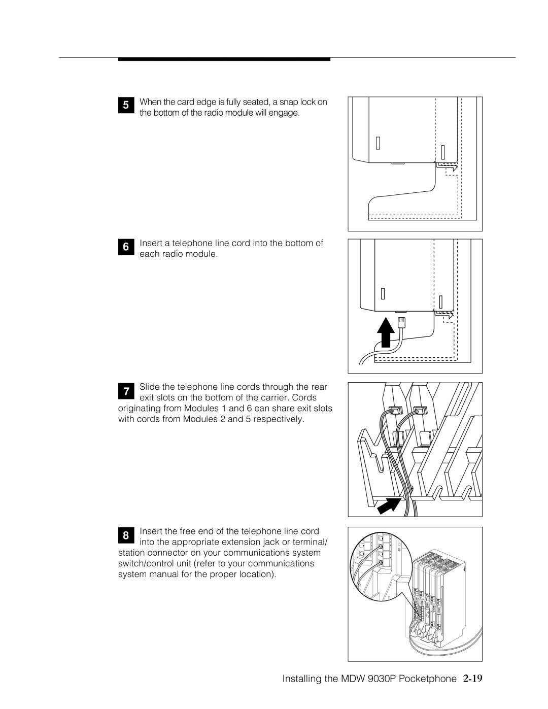
When the card edge is fully seated, a snap lock on the bottom of the radio module will engage.
Insert a telephone line cord into the bottom of each radio module.
7Slide the telephone line cords through the rear exit slots on the bottom of the carrier. Cords
originating from Modules 1 and 6 can share exit slots with cords from Modules 2 and 5 respectively.
8Insert the free end of the telephone line cord into the appropriate extension jack or terminal/
station connector on your communications system switch/control unit (refer to your communications system manual for the proper location).
N | X |
|
S | T |
|
I | E |
|
O | N |
|
N | S |
|
S | I | MUSIC |
| O | |
|
| ON |
| N | HOLD |
| S |
|