6
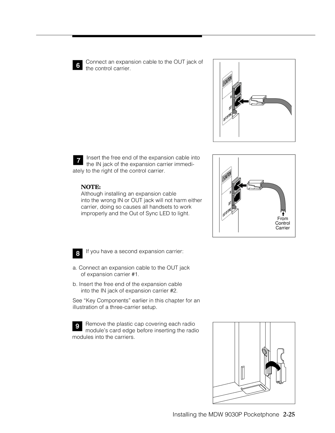
Connect an expansion cable to the OUT jack of the control carrier.
CAUTION | ||
|
| IN |
|
| OUT |
|
| YNC |
OUT | OF | S |
| ||
|
| |
7Insert the free end of the expansion cable into the IN jack of the expansion carrier immedi-
ately to the right of the control carrier.
![]()
![]() CAUTION
CAUTION
NOTE: |
|
|
|
|
|
|
Although installing an expansion cable |
|
|
|
|
| IN |
|
|
|
|
| ||
into the wrong IN or OUT jack will not harm either |
|
|
|
| OUT | |
carrier, doing so causes all handsets to work |
|
|
|
| ||
|
|
|
|
|
| |
|
|
|
| YNC | ||
|
|
|
| |||
|
|
|
|
| ||
improperly and the Out of Sync LED to light. |
| OUT | OF | S | ||
|
|
| ||||
|
|
|
| |||
|
|
|
|
| ||
8If you have a second expansion carrier:
a.Connect an expansion cable to the OUT jack of expansion carrier #1.
b.Insert the free end of the expansion cable into the IN jack of expansion carrier #2.
See “Key Components” earlier in this chapter for an illustration of a
9Remove the plastic cap covering each radio module’s card edge before inserting the radio
modules into the carriers.
From
Control
Carrier