1 |
Hardware Preparation and Installation
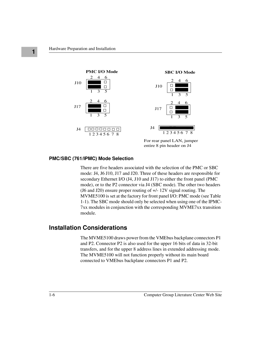
PMC I/O Mode
2 4 6
J10
1 3 5
2 4 6
J17
1 3 5
J4 ![]()
![]()
![]()
![]()
![]()
![]()
![]()
![]()
![]()
![]() 1 2 3 4 5 6 7 8
1 2 3 4 5 6 7 8
SBC I/O Mode
2 4 6
J10
1 3 5
2 4 6
J17
1 3 5
J4
1 2 3 4 5 6 7 8
For rear panel LAN, jumper entire 8 pin header on J4
PMC/SBC (761/IPMC) Mode Selection
There are five headers associated with the selection of the PMC or SBC mode: J4, J6 J10, J17 and J20. Three of these headers are responsible for secondary Ethernet I/O (J4, J10 and J17) to either the front panel (PMC mode), or to the P2 connector via J4 (SBC mode). The other two headers (J6 and J20) ensure proper routing of +/- 12V signal routing. The MVME5100 is set at the factory for front panel I/O: PMC mode (see Table
Installation Considerations
The MVME5100 draws power from the VMEbus backplane connectors P1 and P2. Connector P2 is also used for the upper 16 bits of data in
Computer Group Literature Center Web Site |