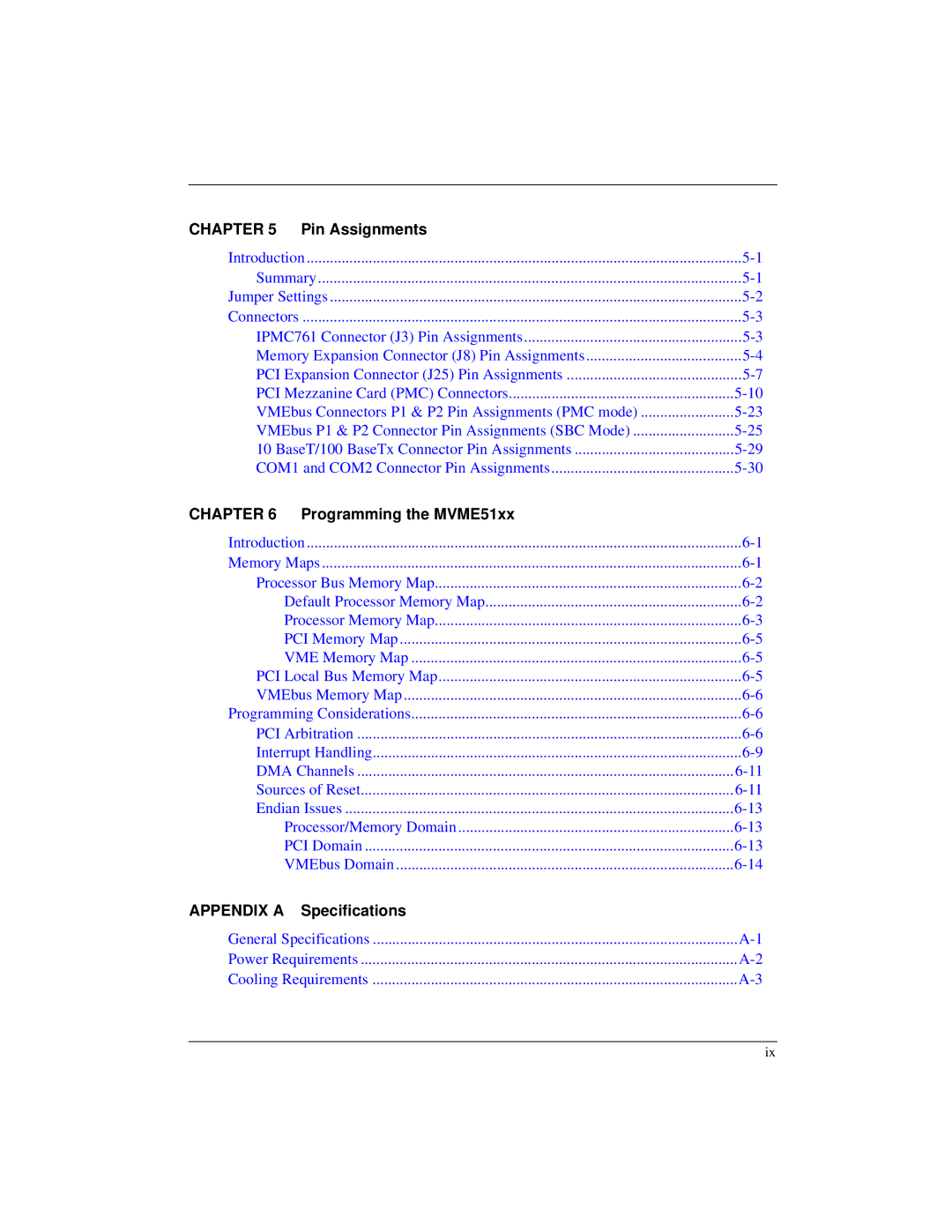
CHAPTER 5 | Pin Assignments |
|
Introduction | ||
Summary | ||
Jumper Settings | ||
Connectors | ||
IPMC761 Connector (J3) Pin Assignments | ||
Memory Expansion Connector (J8) Pin Assignments | ||
PCI Expansion Connector (J25) Pin Assignments | ||
PCI Mezzanine Card (PMC) Connectors | ||
VMEbus Connectors P1 & P2 Pin Assignments (PMC mode) | ||
VMEbus P1 & P2 Connector Pin Assignments (SBC Mode) | ||
10 BaseT/100 BaseTx Connector Pin Assignments | ||
COM1 and COM2 Connector Pin Assignments | ||
CHAPTER 6 Programming the MVME51xx |
| |
Introduction | ||
Memory Maps | ||
Processor Bus Memory Map | ||
| Default Processor Memory Map | |
| Processor Memory Map | |
| PCI Memory Map | |
| VME Memory Map | |
PCI Local Bus Memory Map | ||
VMEbus Memory Map | ||
Programming Considerations | ||
PCI Arbitration | ||
Interrupt Handling | ||
DMA Channels | ||
Sources of Reset | ||
Endian Issues | ||
| Processor/Memory Domain | |
| PCI Domain | |
| VMEbus Domain | |
APPENDIX A | Specifications |
|
General Specifications | ||
Power Requirements | ||
Cooling Requirements | ||
ix
