4 |
Functional Description
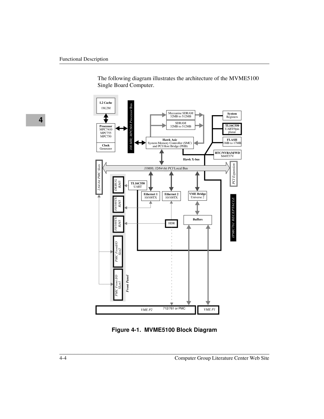
The following diagram illustrates the architecture of the MVME5100 Single Board Computer.
L2 Cache | Bus | |
1M,2M | ||
|
|
|
| Processor |
| Mezzanine SDRAM | System | |
|
|
|
|
| 32MB to 512MB | Registers | |
Processor |
|
| MPC604 |
| SDRAM |
| TL16C550 |
|
|
| 32MB to 512MB | ||||
MPC7410 |
|
|
|
|
|
| UART/9pin |
MPC755 |
|
|
|
|
|
| planar |
|
|
|
|
|
|
| |
MPC750 |
|
| MHz |
| Hawk Asic |
| FLASH |
|
|
|
|
| |||
Clock |
|
| System Memory Controller (SMC) | 1MB to 17MB | |||
|
| 100 | and PCI Host Bridge (PHB) |
|
| ||
Generator |
|
|
|
|
|
| |
|
|
|
|
|
|
| RTC/NVRAM/WD |
|
|
|
|
| Hawk | M48T37V | |
DEBUG | RJ45 |
|
| ExpansionPCI | |||
| 33MHz |
| |||||
|
|
|
|
|
| ||
|
|
| TL16C550 |
|
|
| |
|
|
|
| UART |
|
|
|
|
|
|
| Ethernet 1 | Ethernet 2 | VME Bridge |
|
| 10/100TX10/100TX | RJ45 RJ45 |
| 10/100TX | 10/100TX | Universe 2 | RECEPTACLEIPMC761 |
|
|
|
| Buffers | |||
|
|
|
|
|
|
| |
|
|
|
|
| HDR |
|
|
| PMC FrontI/O | Slot2 |
|
|
|
|
|
| PMC Front I/O | SLot1 | Front Panel |
|
|
|
|
VME P2 | 712/761 or PMC | VME P1 |
|
Figure 4-1. MVME5100 Block Diagram
Computer Group Literature Center Web Site |