Preparation
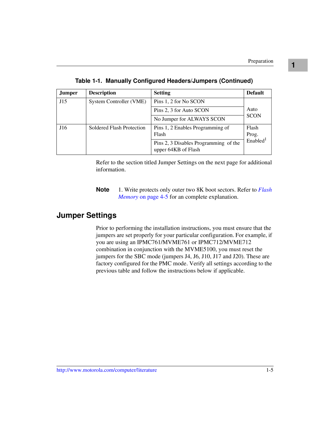
Table 1-1. Manually Configured Headers/Jumpers (Continued)
Jumper | Description | Setting | Default |
|
|
|
|
J15 | System Controller (VME) | Pins 1, 2 for No SCON |
|
|
|
| Auto |
|
| Pins 2, 3 for Auto SCON | |
|
|
| SCON |
|
| No Jumper for ALWAYS SCON | |
|
|
| |
|
|
|
|
J16 | Soldered Flash Protection | Pins 1, 2 Enables Programming of | Flash |
|
| Flash | Prog. |
|
|
| Enabled1 |
|
| Pins 2, 3 Disables Programming of the | |
|
|
| |
|
| upper 64KB of Flash |
|
|
|
|
|
Refer to the section titled Jumper Settings on the next page for additional information.
Note 1. Write protects only outer two 8K boot sectors. Refer to Flash Memory on page
Jumper Settings
Prior to performing the installation instructions, you must ensure that the jumpers are set properly for your particular configuration. For example, if you are using an IPMC761/MVME761 or IPMC712/MVME712 combination in conjunction with the MVME5100, you must reset the jumpers for the SBC mode (jumpers J4, J6, J10, J17 and J20). These are factory configured for the PMC mode. Verify all settings according to the previous table and follow the instructions below if applicable.
1
http://www.motorola.com/computer/literature |