5 |
Pin Assignments
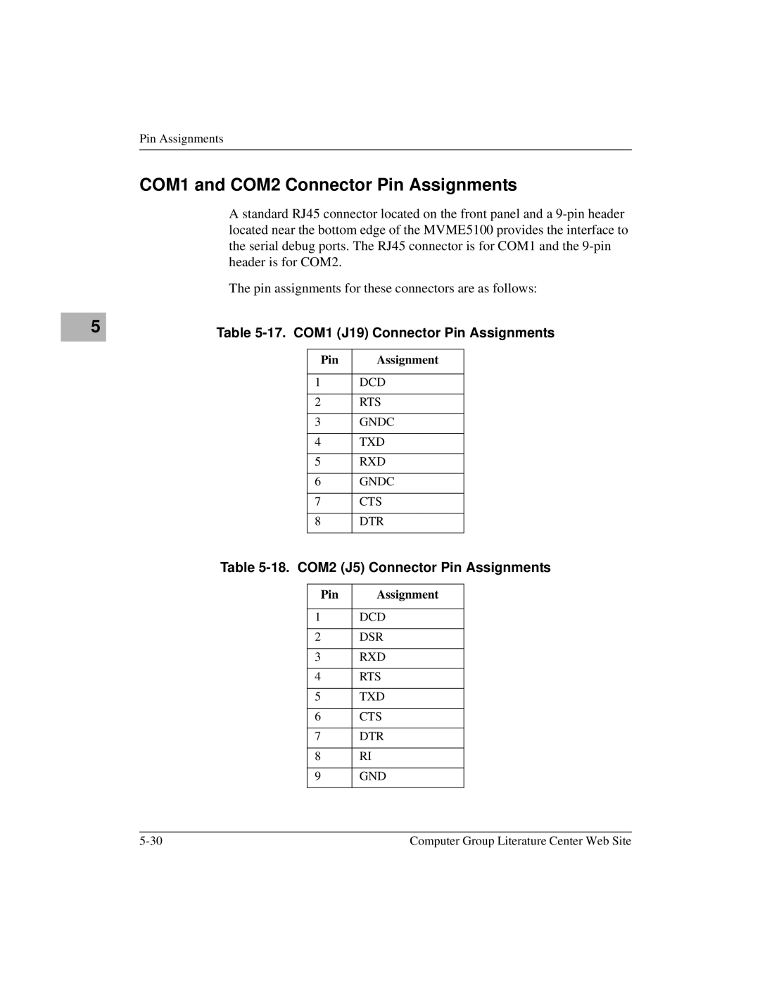
COM1 and COM2 Connector Pin Assignments
A standard RJ45 connector located on the front panel and a
The pin assignments for these connectors are as follows:
Table 5-17. COM1 (J19) Connector Pin Assignments
Pin | Assignment |
|
|
1 | DCD |
|
|
2 | RTS |
|
|
3 | GNDC |
|
|
4 | TXD |
|
|
5 | RXD |
|
|
6 | GNDC |
|
|
7 | CTS |
|
|
8 | DTR |
|
|
Table 5-18. COM2 (J5) Connector Pin Assignments
Pin | Assignment |
|
|
1 | DCD |
|
|
2 | DSR |
|
|
3 | RXD |
|
|
4 | RTS |
|
|
5 | TXD |
|
|
6 | CTS |
|
|
7 | DTR |
|
|
8 | RI |
|
|
9 | GND |
|
|
Computer Group Literature Center Web Site |