Pin Assignments
5
Introduction
This chapter provides information on pin assignments for various jumpers and connectors on the MVME5100 Single Board Computer.
Summary
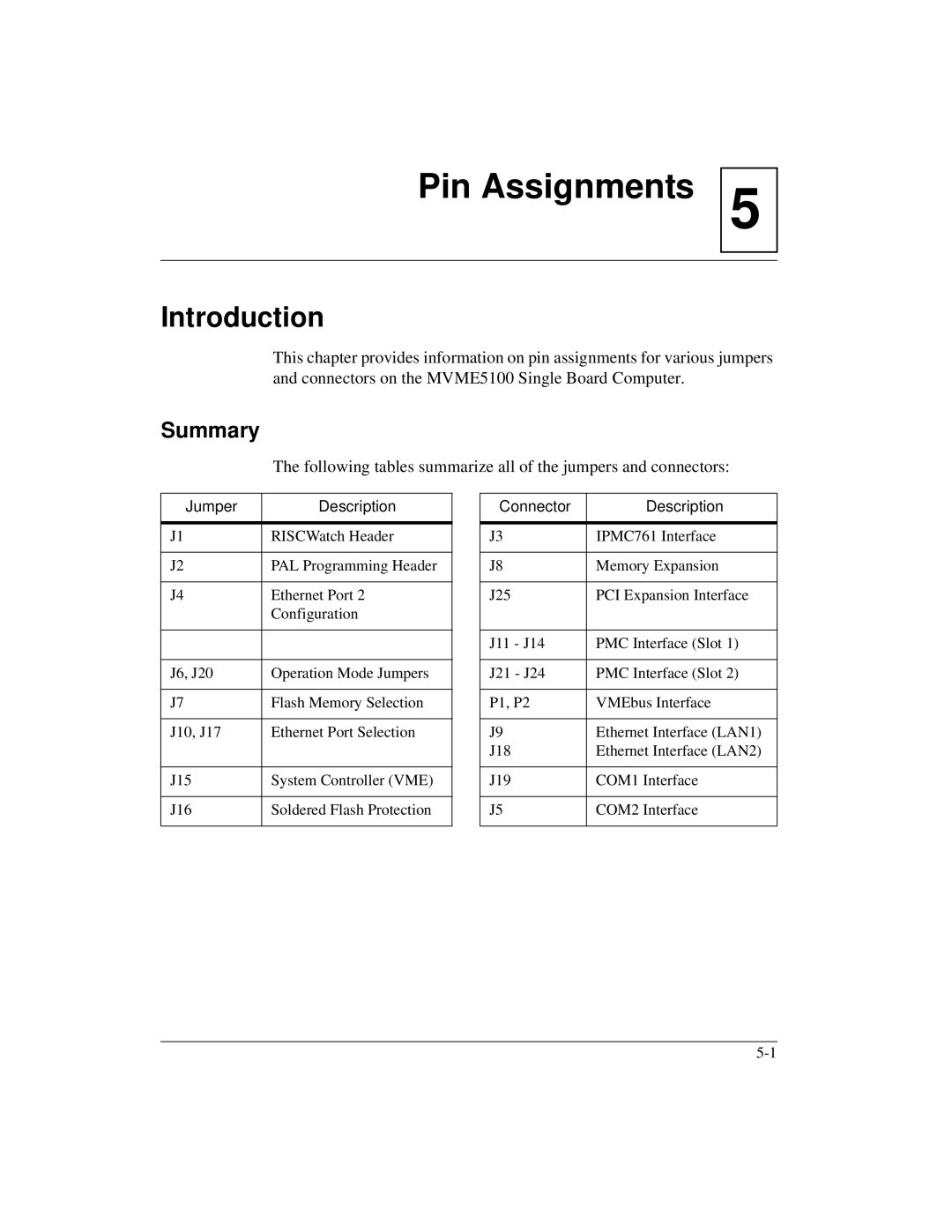
The following tables summarize all of the jumpers and connectors:
Jumper | Description |
|
|
J1 | RISCWatch Header |
|
|
J2 | PAL Programming Header |
|
|
J4 | Ethernet Port 2 |
| Configuration |
|
|
|
|
J6, J20 | Operation Mode Jumpers |
|
|
J7 | Flash Memory Selection |
|
|
J10, J17 | Ethernet Port Selection |
|
|
J15 | System Controller (VME) |
|
|
J16 | Soldered Flash Protection |
|
|
Connector | Description |
|
|
J3 | IPMC761 Interface |
|
|
J8 | Memory Expansion |
|
|
J25 | PCI Expansion Interface |
|
|
J11 - J14 | PMC Interface (Slot 1) |
|
|
J21 - J24 | PMC Interface (Slot 2) |
|
|
P1, P2 | VMEbus Interface |
|
|
J9 | Ethernet Interface (LAN1) |
J18 | Ethernet Interface (LAN2) |
|
|
J19 | COM1 Interface |
|
|
J5 | COM2 Interface |
|
|
