5 |
Pin Assignments
Jumper Settings
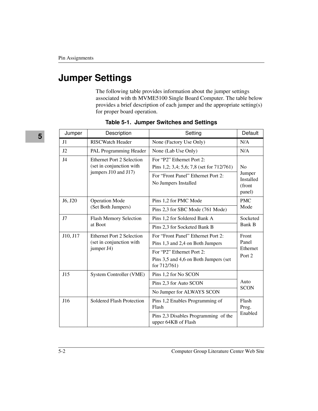
The following table provides information about the jumper settings associated with th MVME5100 Single Board Computer. The table below provides a brief description of each jumper and the appropriate setting(s) for proper board operation.
Table 5-1. Jumper Switches and Settings
Jumper | Description | Setting | Default |
|
|
|
|
J1 | RISCWatch Header | None (Factory Use Only) | N/A |
|
|
|
|
J2 | PAL Programming Header | None (Lab Use Only) | N/A |
|
|
|
|
J4 | Ethernet Port 2 Selection | For “P2” Ethernet Port 2: |
|
| (set in conjunction with | Pins 1,2; 3,4; 5,6; 7,8 (set for 712/761) | No |
| jumpers J10 and J17) |
| Jumper |
| For “Front Panel” Ethernet Port 2: | ||
|
| Installed | |
|
| No Jumpers Installed | |
|
| (front | |
|
|
| |
|
|
| panel) |
|
|
|
|
J6, J20 | Operation Mode | Pins 1,2 for PMC Mode | PMC |
| (Set Both Jumpers) |
| Mode |
| Pins 2,3 for SBC Mode (761 Mode) | ||
|
|
| |
|
|
|
|
J7 | Flash Memory Selection | Pins 1,2 for Soldered Bank A | Socketed |
| at Boot |
| Bank B |
| Pins 2,3 for Socketed Bank B | ||
|
|
| |
|
|
|
|
J10, J17 | Ethernet Port 2 Selection | For “Front Panel” Ethernet Port 2: | Front |
| (set in conjunction with | Pins 1,3 and 2,4 on Both Jumpers | Panel |
| jumper J4) |
| Ethernet |
| For “P2” Ethernet Port 2: | ||
|
| Port 2 | |
|
| Pins 3,5 and 4,6 on Both Jumpers (set | |
|
|
| |
|
| for 712/761) |
|
|
|
|
|
J15 | System Controller (VME) | Pins 1,2 for No SCON |
|
|
|
| Auto |
|
| Pins 2,3 for Auto SCON | |
|
| SCON | |
|
|
| |
|
| No Jumper for ALWAYS SCON | |
|
|
| |
|
|
|
|
J16 | Soldered Flash Protection | Pins 1,2 Enables Programming of | Flash |
|
| Flash | Prog. |
|
|
| Enabled |
|
| Pins 2,3 Disables Programming of the | |
|
|
| |
|
| upper 64KB of Flash |
|
|
|
|
|
Computer Group Literature Center Web Site |