Motorola Single Board Computer manual PMCspan-010 Installation on a PMCspan-002/MVME5100

Models: Single Board Computer MVME5100

1 168
Download 168 pages 1.47 Kb
Page 35
Image 35

Installation

PMCspan-010

1

MVME5100 and

PMCspan-002

Assembly

P3

J3

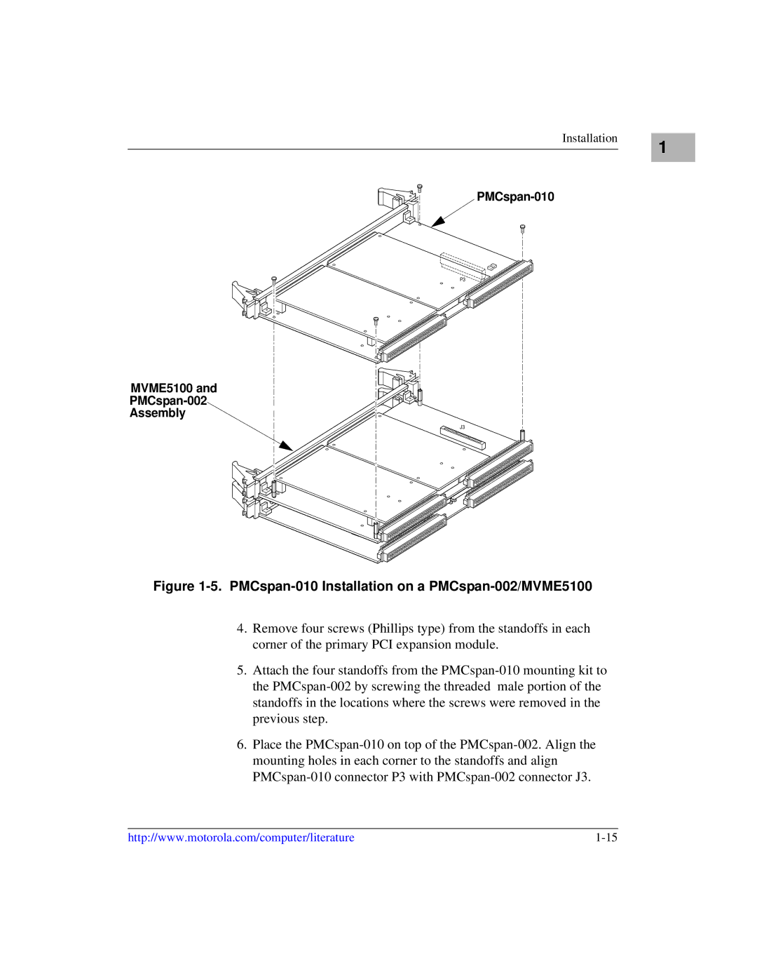
Figure 1-5. PMCspan-010 Installation on a PMCspan-002/MVME5100

4.Remove four screws (Phillips type) from the standoffs in each corner of the primary PCI expansion module.

5.Attach the four standoffs from the PMCspan-010 mounting kit to the PMCspan-002 by screwing the threaded male portion of the standoffs in the locations where the screws were removed in the previous step.

6.Place the PMCspan-010 on top of the PMCspan-002. Align the mounting holes in each corner to the standoffs and align PMCspan-010 connector P3 with PMCspan-002 connector J3.

http://www.motorola.com/computer/literature

1-15

Page 35
Image 35
Motorola Single Board Computer manual PMCspan-010 Installation on a PMCspan-002/MVME5100