4.8 Maintenance
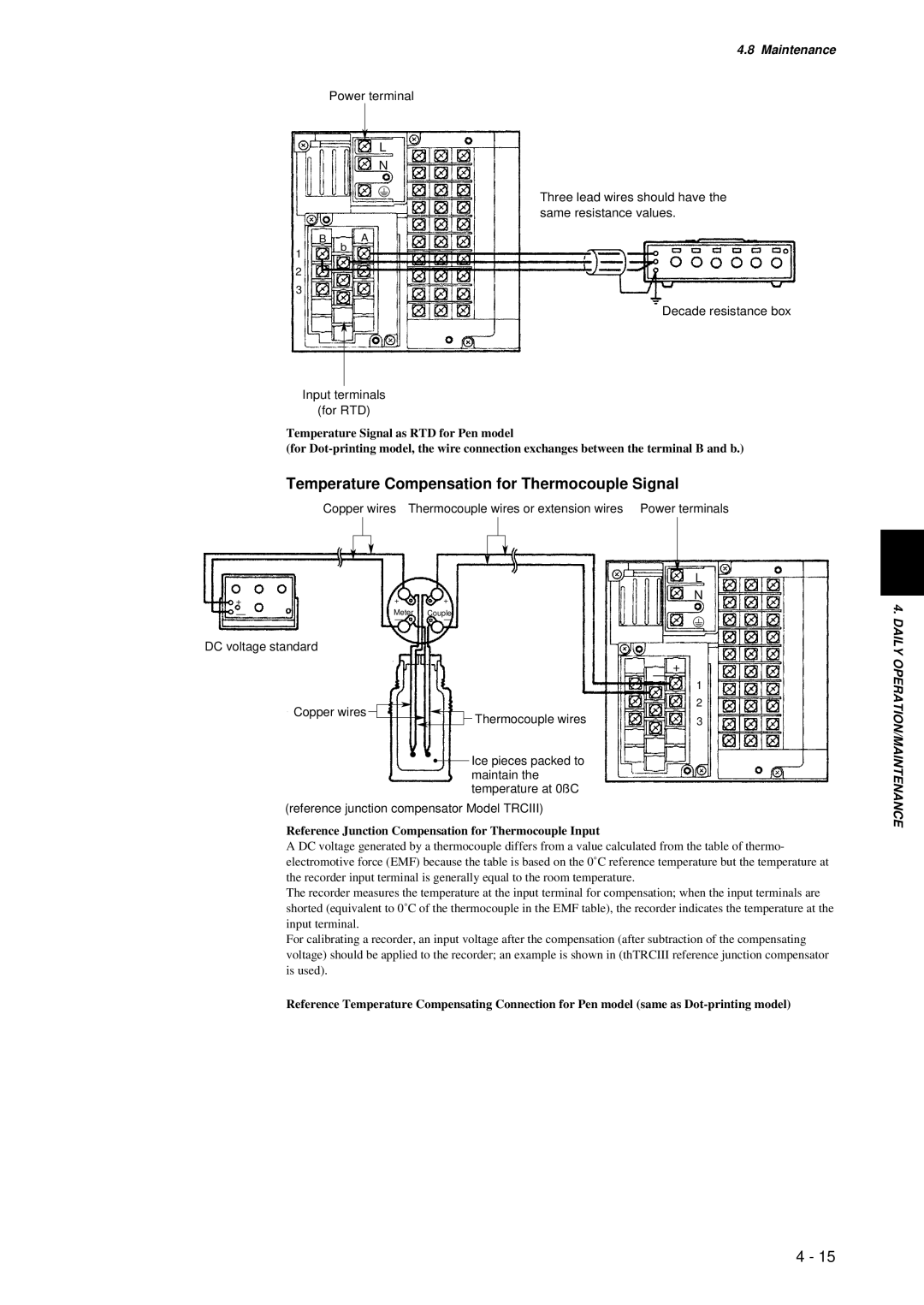
Power terminal
L
N
Three lead wires should have the same resistance values.
B A
1 | b |
| |
2 |
|
3 |
|
Decade resistance box
Input terminals
(for RTD)
Temperature Signal as RTD for Pen model
(for
Temperature Compensation for Thermocouple Signal
Copper wires Thermocouple wires or extension wires Power terminals
|
|
| L |
+ | + | + | N |
| |||
— | Meter | Couple |
|
| — | — |
|
4. DAILY
DC voltage standard
Copper wires ![]()
| — + |
| 1 |
| 2 |
Thermocouple wires | 3 |
![]() Ice pieces packed to maintain the temperature at 0ßC
Ice pieces packed to maintain the temperature at 0ßC
OPERATION/MAINTENANCE
(reference junction compensator Model TRCIII)
Reference Junction Compensation for Thermocouple Input
A DC voltage generated by a thermocouple differs from a value calculated from the table of thermo- electromotive force (EMF) because the table is based on the 0˚C reference temperature but the temperature at the recorder input terminal is generally equal to the room temperature.
The recorder measures the temperature at the input terminal for compensation; when the input terminals are shorted (equivalent to 0˚C of the thermocouple in the EMF table), the recorder indicates the temperature at the input terminal.
For calibrating a recorder, an input voltage after the compensation (after subtraction of the compensating voltage) should be applied to the recorder; an example is shown in (thTRCIII reference junction compensator is used).
Reference Temperature Compensating Connection for Pen model (same as
4 - 15