2.2 Wiring
2.2.2Power Supply Wiring !
(1)The rated power supply voltage for the recorder is follows.
• 100 to 240 V AC
(2)Turn the recorder’s power switch off.
(3)Open the transparent cover of the power terminal after releasing the cover screw.
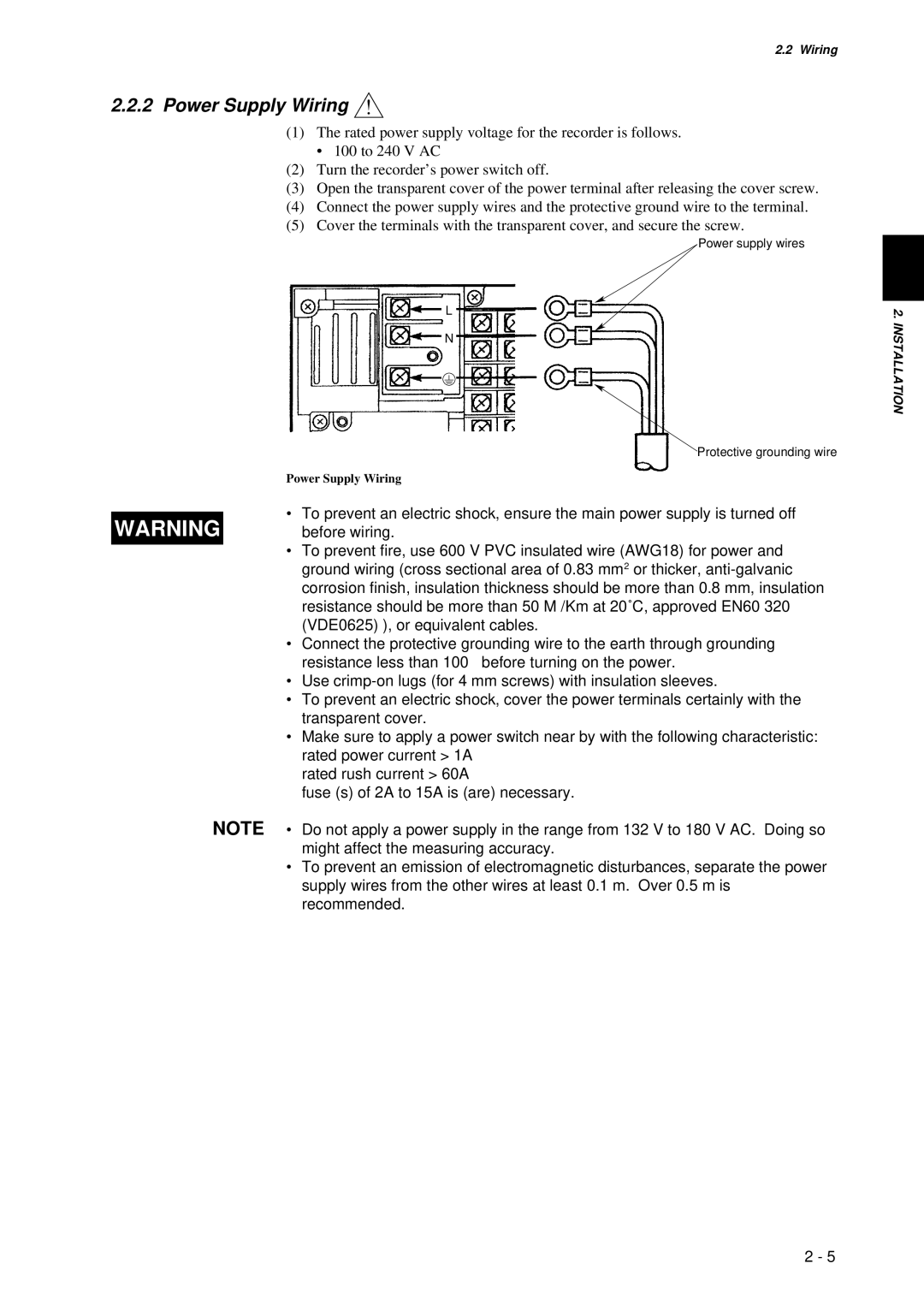
(4)Connect the power supply wires and the protective ground wire to the terminal.
(5)Cover the terminals with the transparent cover, and secure the screw.
Power supply wires
L
N
|
| Protective grounding wire | |
| Power Supply Wiring | ||
| • | To prevent an electric shock, ensure the main power supply is turned off | |
WARNING | |||
| before wiring. | ||
| • | To prevent fire, use 600 V PVC insulated wire (AWG18) for power and | |
|
| ground wiring (cross sectional area of 0.83 mm2 or thicker, | |
|
| corrosion finish, insulation thickness should be more than 0.8 mm, insulation | |
|
| resistance should be more than 50 M /Km at 20˚C, approved EN60 320 | |
|
| (VDE0625) ), or equivalent cables. | |
| • | Connect the protective grounding wire to the earth through grounding | |
|
| resistance less than 100 before turning on the power. | |
| • | Use | |
| • | To prevent an electric shock, cover the power terminals certainly with the | |
|
| transparent cover. | |
| • | Make sure to apply a power switch near by with the following characteristic: | |
|
| rated power current > 1A | |
|
| rated rush current > 60A | |
|
| fuse (s) of 2A to 15A is (are) necessary. | |
NOTE • Do not apply a power supply in the range from 132 V to 180 V AC. Doing so might affect the measuring accuracy.
•To prevent an emission of electromagnetic disturbances, separate the power supply wires from the other wires at least 0.1 m. Over 0.5 m is recommended.
2. INSTALLATION
2 - 5
