CHAPTER 3: Replacing notebook components
Replacing the LCD panel assembly
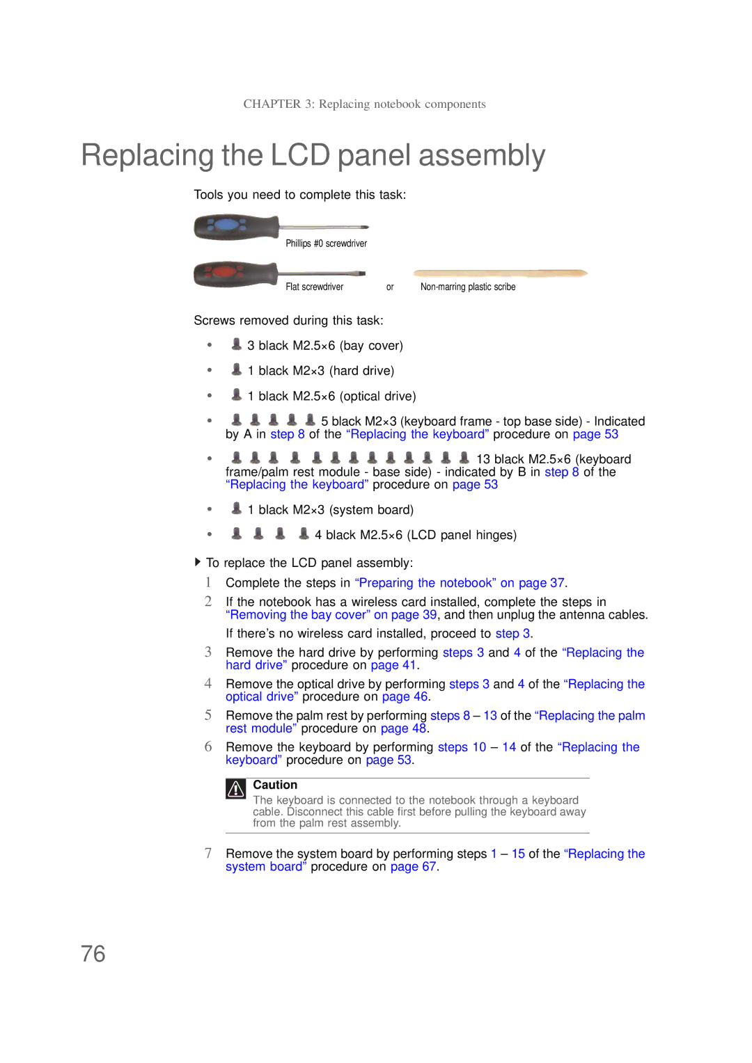
Tools you need to complete this task:
Phillips #0 screwdriver
Flat screwdriver | or |
Screws removed during this task:
•![]() 3 black M2.5×6 (bay cover)
3 black M2.5×6 (bay cover)
•![]() 1 black M2×3 (hard drive)
1 black M2×3 (hard drive)
•![]() 1 black M2.5×6 (optical drive)
1 black M2.5×6 (optical drive)
•![]()
![]()
![]()
![]()
![]() 5 black M2×3 (keyboard frame - top base side) - Indicated by A in step 8 of the “Replacing the keyboard” procedure on page 53
5 black M2×3 (keyboard frame - top base side) - Indicated by A in step 8 of the “Replacing the keyboard” procedure on page 53
•![]()
![]()
![]()
![]()
![]()
![]()
![]()
![]()
![]()
![]()
![]()
![]()
![]() 13 black M2.5×6 (keyboard frame/palm rest module - base side) - indicated by B in step 8 of the “Replacing the keyboard” procedure on page 53
13 black M2.5×6 (keyboard frame/palm rest module - base side) - indicated by B in step 8 of the “Replacing the keyboard” procedure on page 53
•![]() 1 black M2×3 (system board)
1 black M2×3 (system board)
• | 4 black M2.5×6 (LCD panel hinges) |
![]() To replace the LCD panel assembly:
To replace the LCD panel assembly:
1Complete the steps in “Preparing the notebook” on page 37.
2If the notebook has a wireless card installed, complete the steps in “Removing the bay cover” on page 39, and then unplug the antenna cables. If there’s no wireless card installed, proceed to step 3.
3Remove the hard drive by performing steps 3 and 4 of the “Replacing the hard drive” procedure on page 41.
4Remove the optical drive by performing steps 3 and 4 of the “Replacing the optical drive” procedure on page 46.
5Remove the palm rest by performing steps 8 – 13 of the “Replacing the palm rest module” procedure on page 48.
6Remove the keyboard by performing steps 10 – 14 of the “Replacing the keyboard” procedure on page 53.
Caution
The keyboard is connected to the notebook through a keyboard cable. Disconnect this cable first before pulling the keyboard away from the palm rest assembly.
7Remove the system board by performing steps 1 – 15 of the “Replacing the system board” procedure on page 67.
76