CHAPTER 3: Replacing notebook components
Replacing the LCD panel
Tools you need to complete this task:
Phillips #0 screwdriver
Flat screwdriver | or |
Screws removed during this task:
•![]() 3 black M2.5×6 (bay cover)
3 black M2.5×6 (bay cover)
•![]() 1 black M2×3 (hard drive)
1 black M2×3 (hard drive)
•![]() 1 black M2.5×6 (optical drive)
1 black M2.5×6 (optical drive)
•![]()
![]()
![]()
![]()
![]() 5 black M2×3 (keyboard frame - top base side) - Indicated by A in step 8 of the “Replacing the keyboard” procedure on page 53
5 black M2×3 (keyboard frame - top base side) - Indicated by A in step 8 of the “Replacing the keyboard” procedure on page 53
•![]()
![]()
![]()
![]()
![]()
![]()
![]()
![]()
![]()
![]()
![]()
![]()
![]() 13 black M2.5×6 (keyboard frame/palm rest module - base side) - indicated by B in step 8 of the “Replacing the keyboard” procedure on page 53
13 black M2.5×6 (keyboard frame/palm rest module - base side) - indicated by B in step 8 of the “Replacing the keyboard” procedure on page 53
•![]() 1 black M2×3 (system board)
1 black M2×3 (system board)
• | 4 black M2.5×6 (LCD panel hinges) |
•![]()
![]() 2 black M2.5×5 (LCD front panel)
2 black M2.5×5 (LCD front panel)
• | 4 chrome M2.5×4 (LCD panel) |
![]() To replace the LCD panel:
To replace the LCD panel:
1Complete the steps in “Preparing the notebook” on page 37.
2Remove the LCD panel assembly by performing steps 2 – 12 of the “Replacing the LCD panel assembly” procedure on page 76.
3Remove the LCD front panel by performing steps 3 – 5 of the “Replacing the LCD front panel” procedure on page 79.
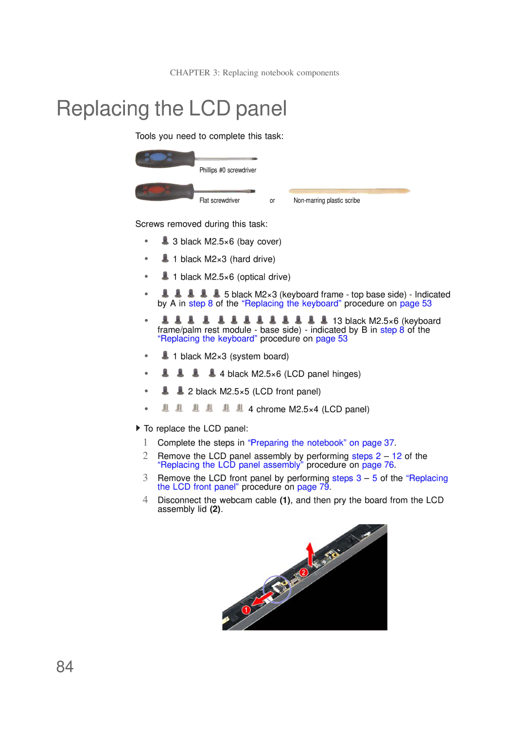
4Disconnect the webcam cable (1), and then pry the board from the LCD assembly lid (2).
84