Revision
CDM-600
Page
Errata a
APP= APP? APP#
Errata B
Errata C
+40 dBc maximum composite, up to -10 dBm, absolute max
Input power range CDM-570 Desired Carrier -30 to -60 dBm
Filename Terrata
BER=10-8 DB 4.2 dB DB 6.8 dB DB 7.9 dB
BER=10-5 DB 4.0 dB DB 6.6 dB DB 7.7 dB
Comtech Turbo Product Codec
AGC Voltage
Errata F
\tpubs\manuals\releasedword\modems\cdm600rev7\errata f.doc
Errata G
\tpubs\manuals\releasedword\modems\cdm600rev7\errata g.doc
\tpubs\manuals\releasedword\modems\cdm600rev7\errata g.doc
This page intentionally left blank
Part Number MN/CDM600.IOM
MN/CDM600.IOM
Table of Contents
CDM-600 Satellite Modem
External Frequency Reference Connector J12
Preface
MN/CDM600.IOM
Front Panel Operation
Forward Error Correction Options
10-1
10.1
10.2
10-3
12.2.3 Alarm 12-3 12.2.4
Buffer Enabled, Rxtx TX Terrestrial or External Clock
10.3 10-3 10.4
10-6
15.1 Modulator 15-1 15.2
13.5
15-3
15.3
Appendix D. ODU Operation
Tables
Figures
Preface
Customer Service
Conventions and References Metric Conversion
About this Manual
Recommended Standard Designations
Reporting Comments or Suggestions Concerning this Manual
Electrical Safety
Fuses
Environmental
Telecommunications Terminal Equipment Directive
Installation
EMC Electromagnetic Compatibility
Limitations of Warranty
Warranty Policy
Exclusive Remedies
Disclaimer
CDM-600
Introduction
Aupc
Standard Features
Software Flash Upgrading
Verification
Data Interfaces
Assembly Description
Major Assemblies
Fast Options and Hardware Options
Order to operate in Turbo TPC Mode
Fast Accessible Options
Fast System Theory
Implementation
Hardware Options
Compatibility
Supporting Hardware and Software
New in this Release
This page is intentionally blank
Unpacking
Installation
Optional Mounting Kit , KT/6228-2
Mounting
Installation of the Optional Mounting Bracket, KT/6228-2
Configuration
Select Internal if Loop
Connect External Cables
Functional Description
CDM-600 Modem Block Diagram
Physical
Introduction
Front Panel
IEC Line Input Connector
Name Ref Des Connector Type Function
Rear Panel
Overhead Data Connector P3A
Rx and Tx if Connectors J1 and J2
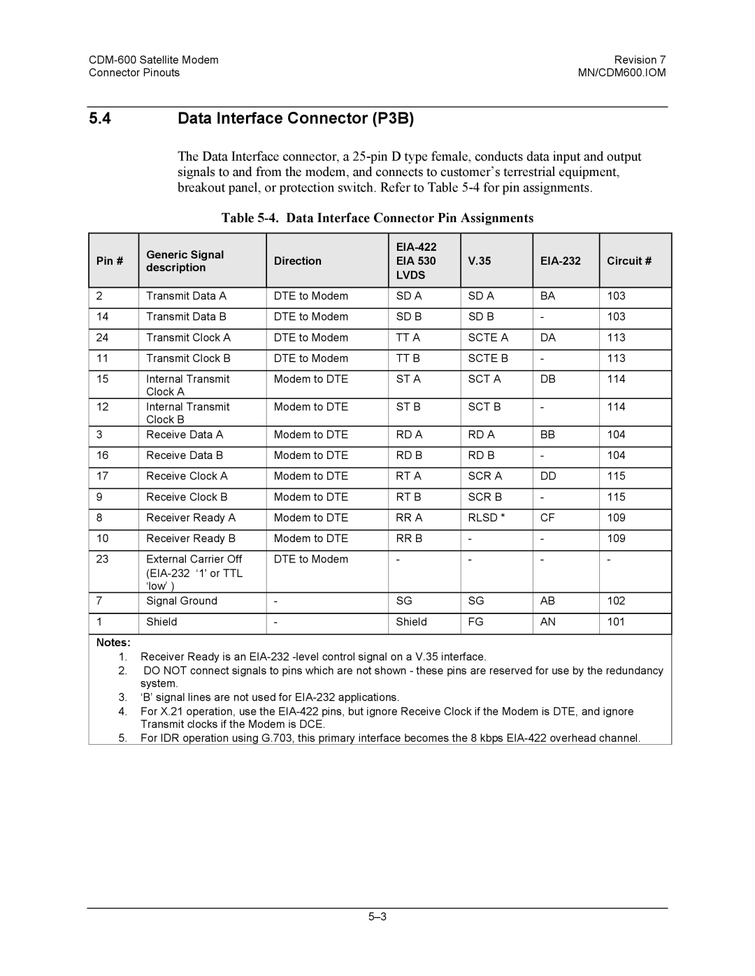
Data Interface Connector P3B
External Reference Connector J9
IDR Alarm connector P5A
Remote Control connector P4B
Form C Traffic Alarm Connector P5B
Auxiliary Serial Connector P6
12 IDI, DDO Connectors J10A and J11A
External Frequency Reference Connector J12
Unbalanced G.703 Tx/Rx J10B and J11B
Dimensional Envelope
Dimensional Envelope
Connector Overview
Connector
Overhead Interface Connector P3A
BNC Connectors
BNC Connectors
Overhead Interface Connector Pin Assignments
RR B
Data Interface Connector Pin Assignments
Remote Control Interface Connector P4B
Audio Interface Connector P4A
Audio Interface Connector Pin Assignments
Remote Control Interface Connector Pin Assignments
Unit Alarms P5B
IDR Backward Alarms Connector P5A
IDR Alarm Interface Connector Pin Assignments
Alarm Interface Connector Pin Assignments
Auxiliary Serial Connector USB Type B Socket
10. Balanced G.703 Interface Connector Pin Assignments
Pin # Signal Function Name Direction
AC Power Connector
Ground Connector
AC Power Specifications
This page is intentionally left blank
Description
Front Panel
Front Panel LED Indicators
LED
Color Condition
Enter
Function of these keys is as follows
Clear
Selection
Menu Trees
Main Menu
Opening Screen
Comtech CDM-600 Open Network Modem Turbo TPC/LDPC VER
Comtech CDM-600E Open Network Modem Turbo TPC/LDPC VER
Config
Config Mode
Config ALL
Mode TX=RS422NONE
ALL = Start STOP, Start
Config TX TX-IF
Config TX
TX-IF Power Encoder MOD Data Scrambler
TX-IF Carrier = on ON,OFF,RTI
Output Power Mode = Manual MANUAL,AUPC
Config TX Power
Output Power Level = -20.0 dBm
Output Power Mode = Aupc MANUAL,AUPC
TPC Turbo Hardware option
Config TX Encoder
REED-SOLOMON Encoding = ON200/180
Config TX Encoder REED-SOLOMON on
Config TX Modulation
MODULATION= Qpsk B,Q,OQ-PSK
FEC Rate = 1/2 1/2,3/4,7/8
Config TX Scrambler
Config TX Data
Data Invert = OFF ON,OFF
TX Scrambler = on ON,OFF Frame Scrambler
Config RX RX-IF
Config RX
Config RX Decoder
REED-SOLOMON Decoding = ON200/180
Config RX Decoder REED-SOLOMON on
Config RX Data
Config RX Demodulation
Demodulation = QPSKB,Q,OQ,8PSK,16QAM
FEC Rate = 1/2 3/4,7/8
RX Descrambler = on ON,OFF Frame Descrambler
Config RX Descrambler
Config Clocks
Config RX EbNo
Config Clocks TX Clock
Clocking TX-CLOCK
Configclocks RX BUFFER/CLOCK
CLK= RX-SAT RX-SAT,TX-TERR,EXT-CLK,INS
BUFFER-SIZE = 00016bytes00002ms Center
Config Clocks EXT-BASEBAND-CLOCK
Config Clocks RX BUFFER/CLOCK Center
Config Clocks EXT-FREQ-REF
Config Clocks Internal Reference
Config Drop & Insert Drop Channel Timeslots
Config Drop & Insert
DRP-TYPE= T1-D4 CHAN/TS LOOP=Y Y/N INS-TYPE= T1-D4 CHAN/TS
DRP-CH 1 2 3 TS 01 02 03
Config Edmac
Config Drop & Insert Insert Channel Timeslots
Config Misc
Edmac Mode = Master IDLE/MASTER/SLAVE Edmac Address =
Config Misc IDR-ESC-TYPE
Config Misc G.703 Code
Config Misc Adpcm Audio Volume
VOLUME=
Config Misc WARM-UP
Config Misc HIGH-RATE-ESC
HIGH-STAB Reference POWER-UP WARM-UP No DELAYINSTANT-ON
INSTANT-ON,DELAY
Onfig Remote Control Interface
Config Remote Control
Config Mask
Config Remote Control Char Format
Config Mask AIS
Configure Alarm Mask AIS Buffer Rxif SAT-ALM TERR-ALM
Config Mask RX-IF
Config Mask Buffer Slip
Config Mask Satellite Alarms
Config Mask Satellite Alarms TX
Config Mask TERR-ALM
Config Mask Satellite Alarms RX
Config Impedance
Config Statistics
Test
Modem Test Mode = Normal NORM,TX-CW,TX-1/0,IF↓,RF↓,DIG↓,I/O↓
Loopback Modes
Information
Info Mode
Infoall
Info ID
Info RX
Info TX
Top Line
Bottom line
Info Edmac
Info Clocks
Info Drop Type
Info Insert Type
Info Alarms Mask
Info Remote
Info Misc
Live UNIT= None NET= Alarms RECV=DEMOD Lock XMT=
Monitor LIVE-ALARMS
Hi-Stab Freq Ref Module Ref Activity Fault
Monitor
Stored Events Clear ALL no NO,YES #199 FT-FRAME Sync
Monitor Stored Events
23/07/01
Network
Monitor Statistics
Configuration 0 Load Store Available
AUPC-PARAMS Remote EbNo=6.8dB Transmit Power INCREASE=1.2dB
Monitor RX Parameters
Monitor AUPC-PARAMS
Utilities
STORE/LOAD Override Configuration
Utilities SET-RTC
Utilities Brightness
Utilities 11 Manual Switch
Utilities Lamp
Utilities Circuit ID
Fast
7 ODU
Fast SET
Fast View
Viterbi
Forward Error Correction Options
Sequential
Viterbi Decoding Summary
For Against
Sequential Decoding Summary
Reed-Solomon Outer Codec
Concatenated RS Coding Summary
Code Rate Mode
PSK/TCM Coding Summary
Trellis Coding Fast Option
TPC and Low Density Parity Check Ldpc coding Introduction
Turbo Product Codec Hardware Option
Ldpc versus TPC
Available TPC and Ldpc Modes
TPC Code Rate/Modulation Data Rate Range
Ldpc Code Rate/Modulation Data Rate Range
End-to-End Processing Delay
Turbo Product Coding Processing Delay Comparison
FEC Mode 64 kbps data rate End-to-end delay, ms
Qpsk Rate 1/2 Viterbi
TPC and Ldpc Summary
Uncoded Operation No FEC
MN/CDM600.IOM
Viterbi
Sequential Decoding
Sequential
Sequential Decoding 2048 kbps
Viterbi with
With
PSK/TCM Rate 2/3
Performance with CDM-600 Firmware Version Or higher
Rate 3/4 QPSK/OQPSK
Rate 7/8 QPSK/OQPSK
Rate 1/2 QPSK/OQPSK
Comtech Turbo Product Codec Rate 21/44 Bpsk
220,200 RS
Differential Encoding
LDPC, BPSK, Qpsk
QPSK/OQPSK/8-PSK
QPSK/OQPSK
Ldpc Rate 3/4 PSK/16-QAM
This page is intentionally blank
Offset Qpsk Operation
CDM-600 Satellite Modem Revision Offset Qpsk Operation
IBS
Open Network Operations
IBS Engineering Service Channel
IBS Clock/data recovery and De-jitter
IBS Framing
IBS Scrambling
2 D&I Framing
1 D&I Primary Data Interfaces
Ccitt G.721
IDR
IDR Primary Data Interfaces
IDR Engineering Service Channel
This page is intentionally blank
Clock Modes and Drop and Insert D&I
Transmit Clocking
Internal Clock
Rx Loop-Timed, RX=TX
Tx Terrestrial
Rx Loop-Timed, Rxtx Asymmetric Loop Timing
External Clock
Buffer Enabled, TX=RX TX Terrestrial or External Clock
Buffer Disabled RX Satellite
Buffer Enabled, Rxtx TX Terrestrial or External Clock
Receive Clocking
Tx Clock Modes
Rx Clock Modes
10-6
Supported T1 and E1 Framing formats
Frame Formats
Time Slot Selection
Drop and Insert Clocking
Drop and Insert Clocking
Rx Buffer Clock = Insert D&I only
Single-Source Multiple Modems
Receive Transmit
Single-Source Multiple Modems Daisy Chain
10-12
Theory Of Operation
Edmac Channel
11.2 M&C Connection
Setup Summary
Drop & Insert ++
Automatic Uplink Power Control
Setting Aupc Parameters
Target Eb/No
Max Range
Alarm
Demod Unlock
Compensation Rate
Monitoring
Overhead Details
ESC++
Effect on Eb/No performance
Available Baud Rates
Flash Upgrading
CDM-600 Satellite Modem Revision Flash Upgrading
Modulator
Summary of Specifications
CDM-600 Satellite Modem Revision Summary of Specifications
Comtech EF Data CDM-600 Transmit
Power Spectral Density Referred to symbol rate
15-4
Codec BER
CDM-600 Satellite Modem Revision Remote Control
Data Interfaces
Automatic Uplink Power Control
Data Rate Ranges
Front panel
Miscellaneous
15-10
EIA-485
Remote Control
Basic Protocol
EIA-232
Packet Structure
Start Of Packet
Address
Instruction Code Qualifier
Instruction Code
End Of Packet
Message Arguments
Alphabetical list of Remote Commands
TFQ= TFQ?
TFQ=
TFQ
TFQ#
TFT= TFT?
TFT=
TFT
TFT#
TCR= TCR?
TCR=
TCR
TCR#
TRS= TRS?
TRS=
TRS
TRS#
TXO= TXO?
TXO=
TXO
TXO#
PLI?
REB?
TCK=
TCK= TCK?
TTA= TTA?
TTA=
TTA
TTA#
TIP= TIP?
TIP=
TIP
TIP#
RFM= RFM?
RFM=
RFM
=IBS RFM# =IDR =INSERT
RMD= RMD?
RMD=
=BPSK RMD
=QPSK RMD# =OQPSK
RDR= RDR?
RDR=
RDR
RDR#
REF= REF?
REF=
REF#
RRS=
IRD= IRD?
IRD=
IRD
IRD#
RVL= RVL?
RVL=
RVL
RVL#
RET= RET?
RET=
RET
RET#
ESC= ESC?
ESC=
ESC
ESC#
EFR= EFR?
EFR=
EFR
EFR#
CTD= CTD?
CTD=
CTD
CTD#
CID= CID?
CID=
CID
CID#
MGC= MGC? MGC=FFF.FFFFDDD
MGC=
MGC? DD.DDDGYRMVSPP
MGC
CST?
CST=
CST
CST#
SSI= SSI?
SSI=
SSI
SSI#
CAS?
CAS=
CAS
CAS#
CAE=
RNE?
CAE?
CAE
IEP#
IEP=
EBN?
RSL?
RED?
BER?
LRS=
LRS= LRS?
FCS?
FCS=BootXXXX
FPGA=ZZZZ
TMP?
EID=abbbcdefgh
EID?
Hardware Bytes
HRV?
FLT?
DNI= DNI?
DNI=
DNI
DNI#
ITS= ITS?
ITS=
ITS
ITS#
OUS?
OUS=xxxxxx
FSW=
Appendix A. Cable Drawings
CDM-600 Satellite Modem Revision Cable Drawings
MN/CDM600.IOM
MN/CDM600.IOM
Measurement
Appendix B. Eb/No
Example
Bpsk Qpsk PSK
This page is intentionally blank
Activation Procedure Serial Number
Appendix C. Fast Activation Procedure
Enter Access Codes
View currently installed features
Functions are
Appendix D. ODU Operation
Modem Main Menu
Menu Trees
Enable
2 ODU
3 ODU
5 ODU,ENABLE,11
4 ODU,ENABLE,11
ODU,ENABLE,11 CSAT#2 ODU,ENABLE,STANDALONE Csat
Redundancy BOX
Configuration
6 ODU,ENABLE,11,CSAT#1
AMP=OFF MUTE=UNMUTED Slope
TX Slope MODE=MANUAL MANUAL,CAL SLOPE=0.3
RX Slope MODE=MANUAL MANUAL,CAL SLOPE=0.2
LNA State
FAULT-LOGIC
Calibrate
LNA-CURRENT
XREF=NO REF-ADJUST=087 RTC=OFF
Misc COLD-START=DISABLE
ODU,ENABLE,11,CSAT#2 Monitor ODU,ENABLE,STANDALONE Csat
13 ODU,ENABLE,11,CSAT#1
Current Status TX RX = OK POWER-SUPPLY
Alarms CURRENT-ALARMS STORED-ALARMS
ODU,ENABLE,11,CSAT#2 Information ODU,ENABLE,STANDALONE Csat
21 ODU,ENABLE,11,CSAT#1
Reading Stored Faults Please Wait
Stored Alarms CLEAR-ALL no NO,YES
Ampoff
Info Txoff
Info Rxon
Unmuted
ENABLE,STANDALONE KST
28 ODU,ENABLE,STANDALONE KST Configuration
27 ODU
29 ODU,ENABLE,STANDALONE KST,CONFIG
30 ODU,ENABLE,STANDALONE KST,CONFIG
31 ODU,ENABLE,STANDALONE KST,CONFIG Misc
33 ODU,ENABLE,STANDALONE KST,INFO Model
32 ODU,ENABLE,STANDALONE KST Information
34 ODU,ENABLE,STANDALONE KST,INFO TX+RX-PARAM
35 ODU,ENABLE,STANDALONE KST,INFO Misc
37 ODU,ENABLE,STANDALONE KST Alarms
36 ODU,ENABLE,STANDALONE KST,INFO Numbers
Index
Statistics
Utilities
MN/CDM600.IOM
Comtech EF Data is an ISO 9001 Registered Company
CDM-600
New Features/Changes
Aupc
Description of D&I with ESC and Aupc
TSR=
MN/CDM600.AA7
Metric Conversions
480 333 2200 Phone 480 333 2161 FAX