Chapter 1 Product Overview
Cisco ONS 15501 Front Panel
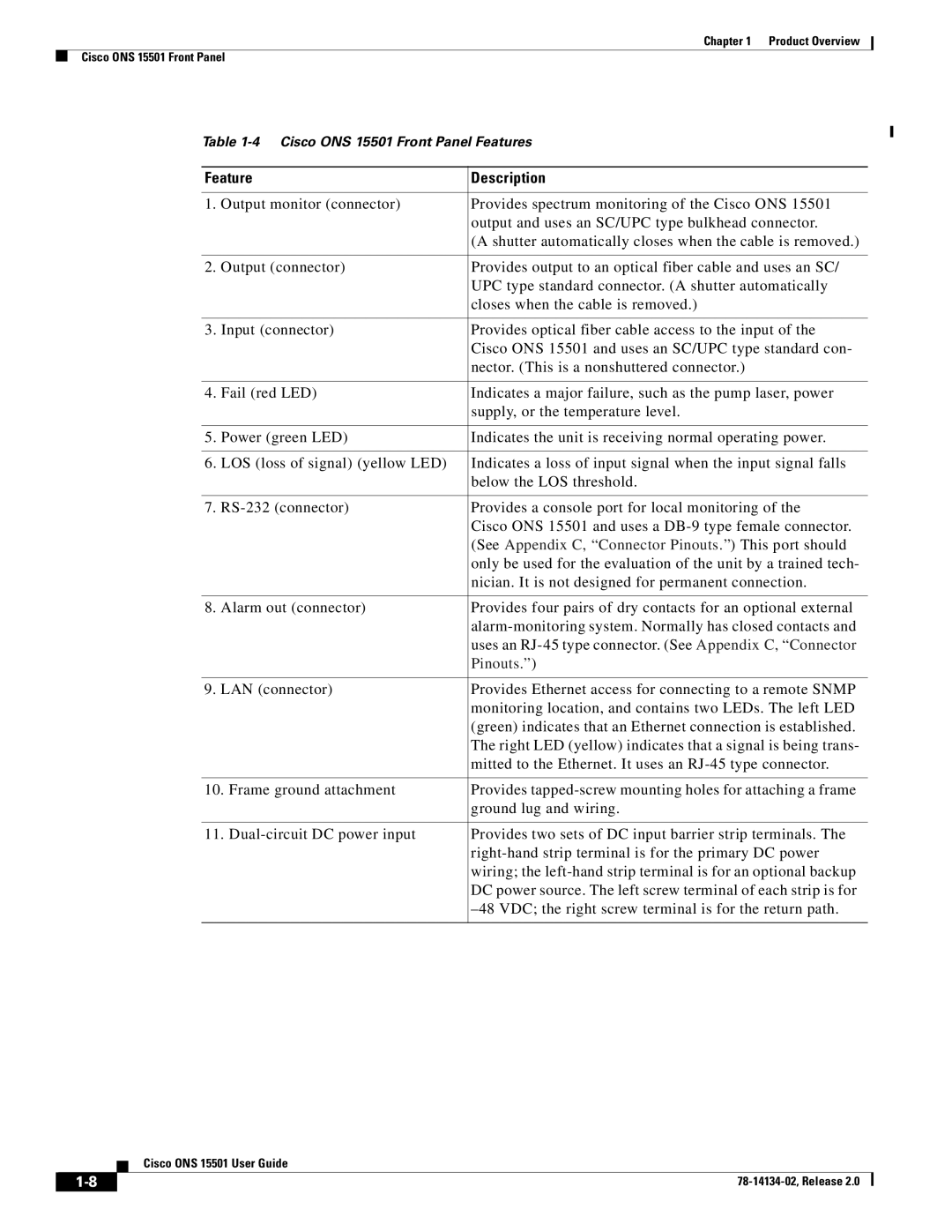
Table
Feature | Description | |
|
|
|
1. | Output monitor (connector) | Provides spectrum monitoring of the Cisco ONS 15501 |
|
| output and uses an SC/UPC type bulkhead connector. |
|
| (A shutter automatically closes when the cable is removed.) |
|
|
|
2. | Output (connector) | Provides output to an optical fiber cable and uses an SC/ |
|
| UPC type standard connector. (A shutter automatically |
|
| closes when the cable is removed.) |
|
|
|
3. | Input (connector) | Provides optical fiber cable access to the input of the |
|
| Cisco ONS 15501 and uses an SC/UPC type standard con- |
|
| nector. (This is a nonshuttered connector.) |
|
|
|
4. | Fail (red LED) | Indicates a major failure, such as the pump laser, power |
|
| supply, or the temperature level. |
|
|
|
5. | Power (green LED) | Indicates the unit is receiving normal operating power. |
|
|
|
6. | LOS (loss of signal) (yellow LED) | Indicates a loss of input signal when the input signal falls |
|
| below the LOS threshold. |
|
|
|
7. | Provides a console port for local monitoring of the | |
|
| Cisco ONS 15501 and uses a |
|
| (See Appendix C, “Connector Pinouts.”) This port should |
|
| only be used for the evaluation of the unit by a trained tech- |
|
| nician. It is not designed for permanent connection. |
|
|
|
8. | Alarm out (connector) | Provides four pairs of dry contacts for an optional external |
|
| |
|
| uses an |
|
| Pinouts.”) |
|
|
|
9. | LAN (connector) | Provides Ethernet access for connecting to a remote SNMP |
|
| monitoring location, and contains two LEDs. The left LED |
|
| (green) indicates that an Ethernet connection is established. |
|
| The right LED (yellow) indicates that a signal is being trans- |
|
| mitted to the Ethernet. It uses an |
|
| |
10. Frame ground attachment | Provides | |
|
| ground lug and wiring. |
|
| |
11. | Provides two sets of DC input barrier strip terminals. The | |
|
| |
|
| wiring; the |
|
| DC power source. The left screw terminal of each strip is for |
|
| |
|
|
|
| Cisco ONS 15501 User Guide |