Cisco Systems 15501 manual Rack-Mounting the Chassis, Optical Connection

Models: 15501

1 128
Download 128 pages 43.78 Kb
Page 29
Image 29

Chapter 2 Installing the Cisco ONS 15501

Rack-Mounting the Chassis

Rack-Mounting the Chassis

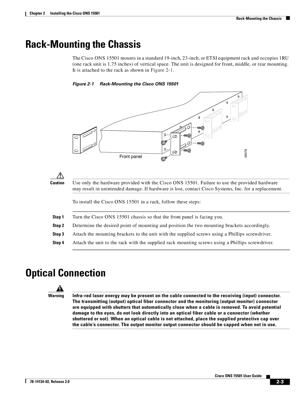
The Cisco ONS 15501 mounts in a standard 19-inch, 23-inch, or ETSI equipment rack and occupies 1RU (one rack unit is 1.75 inches) of vertical space. The unit is designed for front, middle, or rear mounting. It is attached to the rack as shown in Figure 2-1.

Figure 2-1 Rack-Mounting the Cisco ONS 15501

Front panel

68378

Caution Use only the hardware provided with the Cisco ONS 15501. Failure to use the provided hardware may result in unintended damage. If hardware is lost, contact Cisco Systems, Inc. for a replacement.

To install the Cisco ONS 15501 in a rack, follow these steps:

Step 1 Turn the Cisco ONS 15501 chassis so that the front panel is facing you.

Step 2 Determine the desired point of mounting and position the two mounting brackets accordingly.

Step 3 Attach the mounting brackets to the unit with the supplied screws using a Phillips screwdriver.

Step 4 Attach the unit to the rack with the supplied rack mounting screws using a Phillips screwdriver.

Optical Connection

Warning Infra-red laser energy may be present on the cable connected to the receiving (input) connector. The transmitting (output) optical fiber connector and the monitoring (output monitor) connector are equipped with shutters that automatically close when a cable is removed. To avoid potential damage to the eyes, do not look directly into an optical fiber cable or a connector (whether shuttered or not). When an optical cable is not attached, place the supplied protective cap over the cable’s connector. The output monitor output connector should be capped when not in use.


Cisco ONS 15501 User Guide


78-14134-02, Release 2.0


2-3


Page 29
Image 29
Cisco Systems 15501 manual Rack-Mounting the Chassis, Optical Connection