RS±232 Serial Interface
This interface is used with bit serial devices compatible with EIA RS±232C or CCITT V.24 standards. The interface circuit characteristics are compatible with the Electronic Industry Association Specification.
The printer is configured as Data Terminal Equipment (DTE).
The serial data transfer baud rate is selectable from the control panel. The input format consists of a single start bit, 7 or 8 data bits, and one or two stop bits. The operator can set the number of data bits from the control panel. The data bits are interpreted with the least significant bit first. The operator can also set parity checking via the control panel. The printer interface uses a first±in/first±out buffer with the size selectable from the control panel. The asynchronous interface accepts data as it is provided by the host computer.
The maximum cable length from the host computer to the printer is 50 feet.
RS±232 Interface Connector Pin Assignments
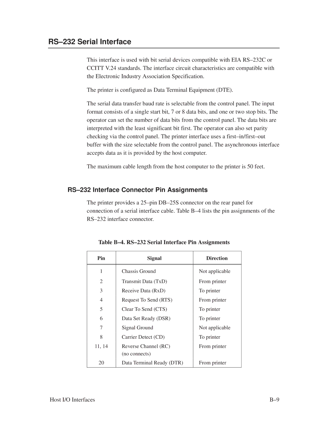
The printer provides a 25±pin DB±25S connector on the rear panel for connection of a serial interface cable. Table B±4 lists the pin assignments of the RS±232 interface connector.
Table B±4. RS±232 Serial Interface Pin Assignments
Pin | Signal | Direction |
|
|
|
|
|
|
1 | Chassis Ground | Not applicable |
| Transmit Data (TxD) | From printer |
2 | ||
|
|
|
3 | Receive Data (RxD) | To printer |
|
|
|
4 | Request To Send (RTS) | From printer |
|
|
|
5 | Clear To Send (CTS) | To printer |
|
|
|
6 | Data Set Ready (DSR) | To printer |
|
|
|
7 | Signal Ground | Not applicable |
|
|
|
8 | Carrier Detect (CD) | To printer |
|
|
|
11, 14 | Reverse Channel (RC) | From printer |
| (no connects) |
|
|
|
|
20 | Data Terminal Ready (DTR) | From printer |
|
|
|
Host I/O Interfaces | B±9 |
