Chapter 2: Installation
Back panel overview
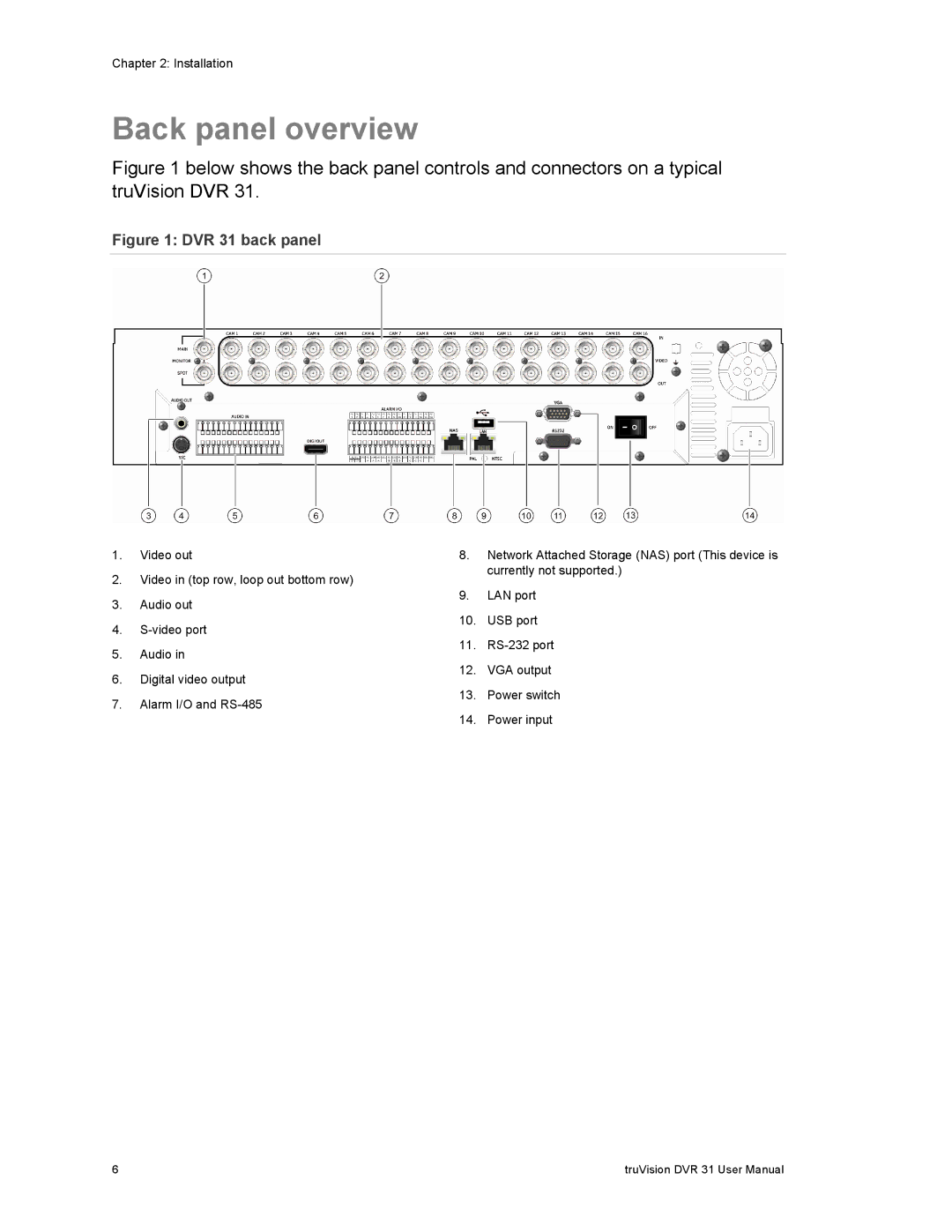
Figure 1 below shows the back panel controls and connectors on a typical truVision DVR 31.
Figure 1: DVR 31 back panel
1.Video out
2.Video in (top row, loop out bottom row)
3.Audio out
4.
5.Audio in
6.Digital video output
7.Alarm I/O and
8.Network Attached Storage (NAS) port (This device is currently not supported.)
9.LAN port
10.USB port
11.
12.VGA output
13.Power switch
14.Power input
6 | truVision DVR 31 User Manual |