User’s Guide
동봉된 CD 안에 한국어 매뉴얼이 있습니다
Contents
Web Interface
Monitor the UPS and Configure Shutdowns
Logs
Administration Notification
Troubleshooting
Appendix a List of Supported Commands
Product Description
Features
Introduction
Network management features
Internal Management Features
Initial setup
Overview
Access priority for logging on
Types of user accounts
How to Recover from a Lost Password
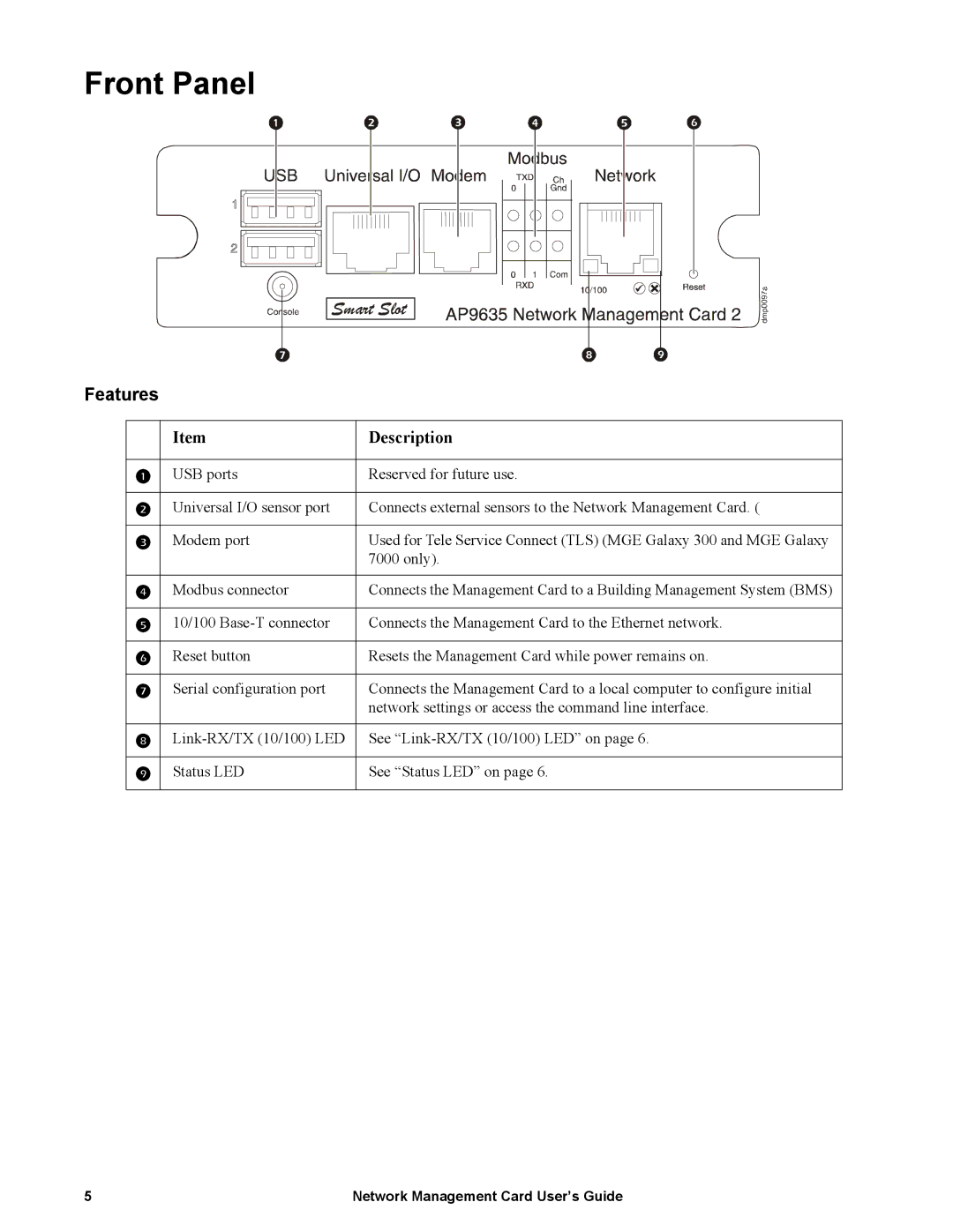
Front Panel
Description
Link-RX/TX 10/100 LED
Status LED
Condition Description
Network interface watchdog mechanism
Watchdog Features
Resetting the network timer
Remote access to the command line interface
Command Line Interface
How To Log On
Information and status fields
Main Screen
Sample main screen
Two fields report when you logged in, by date and time
Command syntax
Using the Command Line Interface
Entering commands
Syntax examples
Command Response Codes
Code Error message
About
Command Descriptions
Alarmcount
Option Arguments Description
Boot
Option Argument Description
Console
Date
Dir
Delete
Argument Description
Dns
Exit
Eventlog
Key Description
Format
Help
Ftp
Option Argument Definition
Modbus
Ping
Netstat
Ntp
Quit
PortSpeed
Prompt
Reboot
Radius
System
ResetToDef
Snmp, snmp3
Tcpip
Tcpip6
Tls
Uio
Ups
User
XferStatus
Web
XferINI
Supported Web browsers
Web Interface
Introduction
Error Message Browser Cause of the Error
URL address formats
Icon Description
Home
Quick status icons
Recent Device Events
Menus
How to Use the Tabs, Menus, and Links
Tabs
Quick Links
Operating state
Monitor the UPS and Configure Shutdowns
Overview
Operating State Icon Description
Model-specific status displayed
Status
Recent UPS Events
PowerChute Option
PowerChute Network Shutdown clients
PowerChute Network Shutdown configuration parameters
Parameter Description
About Option
Environmental Monitoring
Heading Displayed Information
Brief status
Temperature and Humidity
Detailed status and configuration
Threshold Description
UPS Network Management Card 2 User’s Guide
Input Contacts
Output Relay
About
Configuring the UPS or output to respond to an input alarm
Configuring the Control Policy
Configuring an output to respond to an event
Event log
Logs
Use the Event and Data Logs
Launch Log in New Window button
Data log
To display the data log Logs Data log
To set the data collection interval Logs Data interval
How to use FTP or SCP to retrieve log files
Scp username@hostnameoripaddressevent.csv ./event.csv
Syslog servers
Authentication
Administration Security
Setting user access
Local Users
Radius Setting Definition
Radius
Configuring a Radius server on Unix with shadow passwords
Configuring the Radius Server
Summary of the configuration procedure
Supported Radius servers
Inactivity Timeout
TCP/IP settings
Administration Network Features
TCP/IP and Communication Settings
Setting Description
Dhcp response options
APC Cookie. Tag 1, Len 4, Data 1APC
Ping Response
Port Speed
DNS
Query Type Selected Query Question to Use
Web
Option Description
Console
Snmp
SNMPv1
SNMPv3
Modbus
FTP Server
Event Actions
Administration Notification
Configuring event actions
Types of notification
Network Management Card User’s Guide
Active, Automatic, Direct Notification
Mail notification
Identify up to four e-mail recipients
Snmp traps
Snmp Trap Test
Syslog
Remote Monitoring Service
Setting Definition
Syslog Settings Path Logs Syslog settings
Set the Date and Time
Administration General Options
Identification
Method
Use an .ini File
Daylight saving
Specify a default login
Event Log, Temperature Units, and Log-In
Change the default temperature scale
Color-code event log text
About the Management Card
Reset the Management Card
Configure Links
Action Definition
How to use the Wizard to configure TCP/IP settings
Device IP Configuration Wizard
Capabilities, Requirements, and Installation
Installation
Select Remotely over the network, and click Next
Configure the basic TCP/IP settings remotely
Use the Wizard
Configure or reconfigure the TCP/IP settings locally
Select Locally through the serial port, and click Next
Contents of the .ini file
How to Export Configuration Settings
Summary of the procedure
Detailed procedures
Ftp put filename.ini
Messages in config.ini
Upload Event and Error Messages
Event and its error messages
Errors generated by overridden values
Related Topics
Benefits of upgrading firmware
How to Upgrade Firmware
File Transfers
Firmware files Network Management Card
Use FTP or SCP to upgrade one Management Card
Firmware File Transfer Methods
How to upgrade multiple Management Cards
Use Xmodem to upgrade one Management Card
Use a USB drive to transfer the files
Verifying Upgrades and Updates
Verify the version numbers of installed firmware
Verify the success or failure of the transfer
Adding and Changing Language Packs
Problem Solution
Troubleshooting
Management Card Access Problems
Snmp Issues
GET
Appendix a List of Supported Commands
Network Management Card User’s Guide
Network Management Card User’s Guide
Non-transferable warranty Exclusions
Two-Year Factory Warranty
Terms of warranty
Warranty claims
APC Worldwide Customer Support
990-3197B-001 2011