11. Modbus TCP server
11. 8. “Read/Write Multiple Registers” (23 = 16#17) function
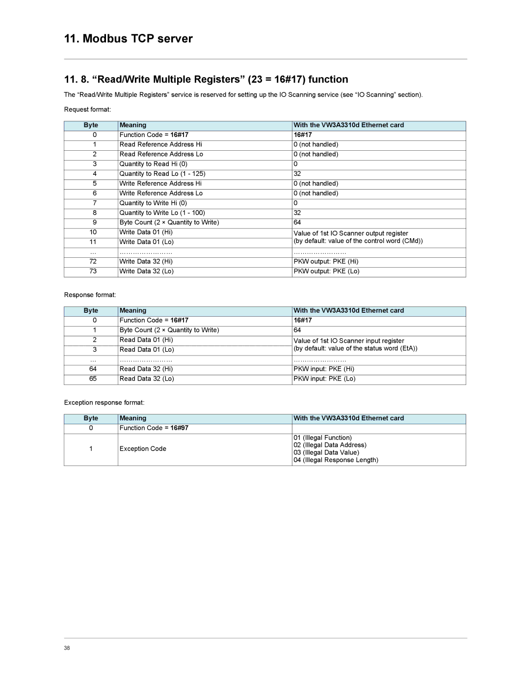
The “Read/Write Multiple Registers” service is reserved for setting up the IO Scanning service (see “IO Scanning” section).
Request format: |
|
|
| |
|
|
| ||
Byte | Meaning | With the VW3A3310d Ethernet card | ||
0 | Function Code = 16#17 | 16#17 | ||
1 | Read Reference Address Hi | 0 (not handled) | ||
2 | Read Reference Address Lo | 0 (not handled) | ||
3 | Quantity to Read Hi (0) | 0 |
| |
4 | Quantity to Read Lo (1 - 125) | 32 |
| |
5 | Write Reference Address Hi | 0 (not handled) | ||
6 | Write Reference Address Lo | 0 (not handled) | ||
7 | Quantity to Write Hi (0) | 0 |
| |
8 | Quantity to Write Lo (1 - 100) | 32 |
| |
9 | Byte Count (2 × Quantity to Write) | 64 |
| |
10 | Write Data 01 (Hi) | Value of 1st IO Scanner output register | ||
11 | Write Data 01 (Lo) | (by default: value of the control word (CMd)) | ||
… | …………………… | …………………… | ||
72 | Write Data 32 (Hi) | PKW output: PKE (Hi) | ||
73 | Write Data 32 (Lo) | PKW output: PKE (Lo) | ||
Response format: |
|
|
| |
|
|
| ||
Byte | Meaning | With the VW3A3310d Ethernet card | ||
0 | Function Code = 16#17 | 16#17 | ||
1 | Byte Count (2 × Quantity to Write) | 64 |
| |
2 | Read Data 01 (Hi) | Value of 1st IO Scanner input register | ||
|
| (by default: value of the status word (EtA)) | ||
3 | Read Data 01 (Lo) | |||
… | …………………… | …………………… | ||
64 | Read Data 32 (Hi) | PKW input: PKE (Hi) | ||
65 | Read Data 32 (Lo) | PKW input: PKE (Lo) | ||
Exception response format: |
|
| ||
|
|
| ||
Byte | Meaning | With the VW3A3310d Ethernet card | ||
0 | Function Code = 16#97 |
|
| |
|
| 01 | (Illegal Function) | |
1 | Exception Code | 02 | (Illegal Data Address) | |
03 | (Illegal Data Value) | |||
|
| |||
|
| 04 | (Illegal Response Length) | |
|
|
|
| |
38
