Manuals
/
Brands
/
Computer Equipment
/
Network Card
/
Schneider Electric
/
Computer Equipment
/
Network Card
Schneider Electric
VW3A3310d
- page 78
1
78
80
80
Download
80 pages, 1.34 Mb
78
20. Setup using ProWORX NxT
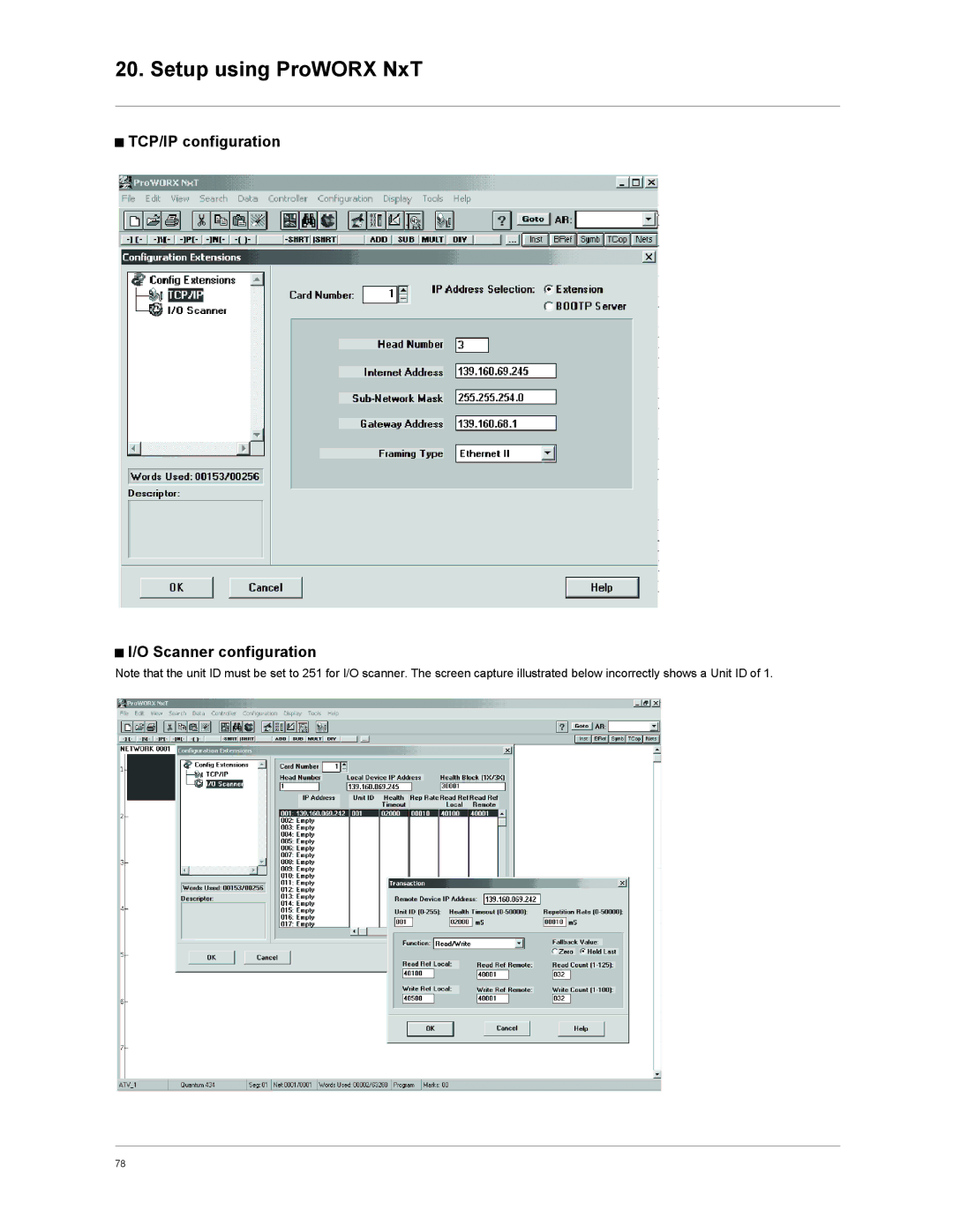
b
TCP/IP configuration
b
I/O Scanner configuration
Note that the unit ID must be set to 251 for I/O scanner. The screen capture illustrated below incorrectly shows a Unit ID of 1
.
Contents
Main
Page
Page
Table of contents
1. Important Information
CAUTION
2. Before you begin
DANGER
HAZARD OF ELECTRIC SHOCK, EXPLOSION, OR ARC FLASH
DAMAGED EQUIPMENT
LOSS OF CONTROL
3. Documentation structure
b Installation Manual
b Programming Manual
Installation and Programming Manuals
4. Introduction
4. 1. Presentation
4. 2. Notation
Drive terminal displays
Formats
CAUTION
6. Connecting to the Ethernet network
6. 1. Card RJ45 connector pinout
6. 2. Example of connection to an Ethernet network
8........................1
6. Connecting to the Ethernet network
6. 3. Ethernet network connection elements
Hubs and switches
Connecting cables
7. 1. Access to Ethernet menu via graphic display terminal
7. 2. Access to Ethernet menu via the integrated display terminal
7. 3. Ethernet menu parameters
Page
Page
8. 1. List of functions to be configured
8. 2. Configuring IP addresses
b Assigning IP addresses
b Entering IP addresses in the terminal
b Configuring BOOTP
b Configuring FDR
8. 3. Reserving control
8. 4. Configuring IO Scanning
8. 5. Configuring the control
b Control via Ethernet in I/O profile
b Control via Ethernet or the terminals in I/O profile
b Control via Ethernet in CiA402 (Drivecom) profile
b Control via Ethernet or the terminals in CiA402 profile
b Command in CiA402 (Drivecom) profile via Ethernet and setpoint switching at the terminals
8. 6. Configuring communication interruption management
b Communication monitoring
b Network management
b Communication
b Drive response
8. 7. Configuring monitored parameters
9. 1. Signalling LEDs
1.1 1.2 1.3 1.4 1.5 2.1 2.2 2.3 2.4 2.5
9. 2. Available information
9. 3. Monitoring the control
pppp
pp
9. 4. Troubleshooting communication interruptions
b Communication monitoring
9. 5. Troubleshooting the card
10. Software setup
10. 1. List of services supported
10. 2. TCP connections
11. 1. Modbus TCP frames
11. 2. Drive Modbus servers
11. 3. Ethernet card parameters
Page
Page
11. 4. List of Modbus functions supported
11. 5. Read Holding Registers (3) function
11. 6. Write Single Register (6) function
11. 7. Write Multiple Registers (16 = 16#10) function
11. 8. Read/Write Multiple Registers (23 = 16#17) function
11. 9. Read Device Identification (43 = 16#2B) function
12. IO Scanning service
12. 1. Presentation
12. 2. Periodic variables
12. IO Scanning service
12. 3. Address table
13. 1. Presentation
13. 2. Local configuration
13. 3. Downloaded configuration
b First use
b Replacing a drive
13. 4. Periodic saving
13. 5. Other commands
13. 6. Configuration file
FDR Configuration File
b Limitations
14. 1. Web server functions
14. 2. Applets
Page
14. 5. Web server user interface
14. 6. Home menu
14. 7. Monitoring menu
14. 8. Altivar Viewer page
14. 9. Data Viewer page
14. 10. Altivar Chart page
14. 11. Diagnostics menu
Page
14. 14. HTTP password and Data write password pages
14. 15. FDR Agent page
Page
14. 16. IO Scanner page
b Enabling IO Scanning
b Assigning the IO Scanning periodic variables
Page
14. 17. E-mail page
Page
15. FTP server
b Access
15. FTP server
b Functions
b File system
b Principle
b File management
b Web server
b Standard web server resources
Page
17. SNMP agent
b Objects handled
Page
b BOOTP configuration
b Configuring Modbus messaging
Page
Page
b Configuring the DHCP address server (FDR)