Issue 10/06 | 6 Commissioning |
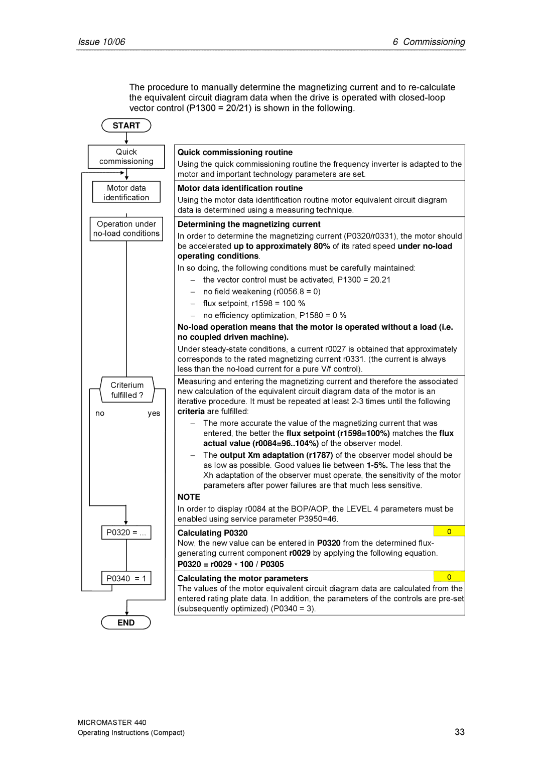
The procedure to manually determine the magnetizing current and to
START
Quick
commissioning
Motor data
identification
Operation under
Criterium
fulfilled ?
no yes
P0320 = ...
P0340 = 1
END
Quick commissioning routine
Using the quick commissioning routine the frequency inverter is adapted to the motor and important technology parameters are set.
Motor data identification routine
Using the motor data identification routine motor equivalent circuit diagram data is determined using a measuring technique.
Determining the magnetizing current
In order to determine the magnetizing current (P0320/r0331), the motor should be accelerated up to approximately 80% of its rated speed under
In so doing, the following conditions must be carefully maintained:
−the vector control must be activated, P1300 = 20.21
−no field weakening (r0056.8 = 0)
−flux setpoint, r1598 = 100 %
−no efficiency optimization, P1580 = 0 %
Under
Measuring and entering the magnetizing current and therefore the associated new calculation of the equivalent circuit diagram data of the motor is an iterative procedure. It must be repeated at least
−The more accurate the value of the magnetizing current that was entered, the better the flux setpoint (r1598=100%) matches the flux actual value (r0084=96..104%) of the observer model.
−The output Xm adaptation (r1787) of the observer model should be as low as possible. Good values lie between
NOTE
In order to display r0084 at the BOP/AOP, the LEVEL 4 parameters must be enabled using service parameter P3950=46.
Calculating P0320 |
| 0 |
Now, the new value can be entered in P0320 from the determined flux- |
| |
generating current component r0029 by applying the following equation. |
| |
P0320 = r0029 * 100 / P0305 |
| |
Calculating the motor parameters |
| 0 |
The values of the motor equivalent circuit diagram data are calculated from the entered rating plate data. In addition, the parameters of the controls are
MICROMASTER 440 | 33 |
Operating Instructions (Compact) |