6 Commissioning | Issue 10/06 |
6.4.18.6 Dynamic braking
The following settings should always be made: |
| |
¾ The Vdc_max controller | P1240 = 0 | (def.: P1240 = 1) |
¾ The compound brake | P1236 = 0 | (def.: P1236 = 0) |
¾ Resistor brake activated | P1237 > 0 | (def.: P1237 = 0) |
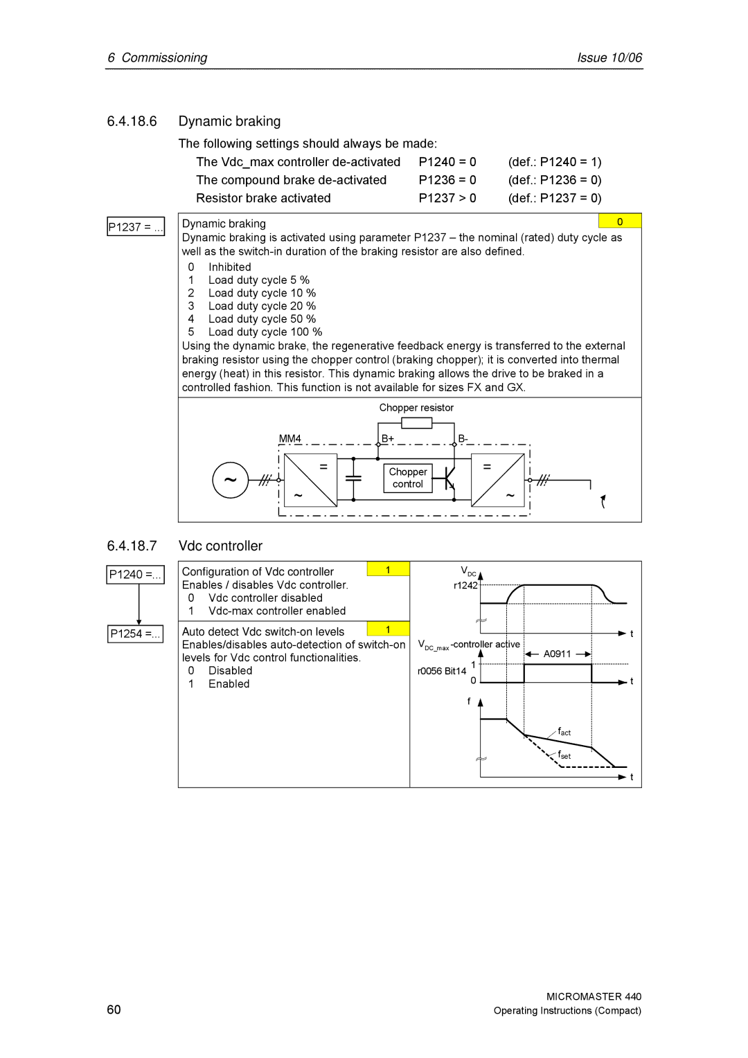
P1237 = ...
Dynamic braking | 0 |
Dynamic braking is activated using parameter P1237 – the nominal (rated) duty cycle as well as the
0Inhibited
1Load duty cycle 5 %
2Load duty cycle 10 %
3Load duty cycle 20 %
4Load duty cycle 50 %
5Load duty cycle 100 %
Using the dynamic brake, the regenerative feedback energy is transferred to the external braking resistor using the chopper control (braking chopper); it is converted into thermal energy (heat) in this resistor. This dynamic braking allows the drive to be braked in a controlled fashion. This function is not available for sizes FX and GX.
|
| Chopper resistor |
|
| MM4 | B+ | B- |
~ | = | Chopper | = |
~ | control | ~ | |
|
|
6.4.18.7
P1240 =...
P1254 =...
Vdc controller
Configuration of Vdc controller | 1 | VDC |
| |
Enables / disables Vdc controller. |
| r1242 |
| |
0 | Vdc controller disabled |
|
|
|
1 |
|
|
| |
Auto detect Vdc | 1 | VDC_max | t | |
Enables/disables | A0911 | |||
levels for Vdc control functionalities. |
| r0056 Bit14 1 | ||
0 | Disabled |
|
| |
1 | Enabled |
| 0 | t |
|
|
| ⏐f⏐ |
|
|
|
|
| fact |
|
|
|
| fset |
|
|
|
| t |
60 | MICROMASTER 440 |
Operating Instructions (Compact) |