Issue 10/06 | 2 Electrical Installation |
2.3Control terminals
Terminal | Designation | Function |
|
|
|
|
|
1 | – | Output +10 V |
|
|
|
|
|
2 | – | Output 0 V |
|
3 | ADC1+ | Analog input 1 (+) |
|
|
|
|
|
4 | ADC1– | Analog input 1 |
|
|
|
|
|
5 | DIN1 | Digital input 1 |
|
|
|
|
|
6 | DIN2 | Digital input 2 |
|
7 | DIN3 | Digital input 3 |
|
|
|
|
|
8 | DIN4 | Digital input 4 |
|
|
|
|
|
9 | – | Isolated output +24 V / max. 100 mA |
|
10 | ADC2+ | Analog input 2 (+) |
|
|
|
|
|
11 | ADC2– | Analog input 2 |
|
|
|
|
|
12 | DAC1+ | Analog output 1 (+) |
|
|
|
|
|
13 | DAC1– | Analog output 1 |
|
14 | PTCA | Connection for PTC / KTY84 |
|
|
|
|
|
15 | PTCB | Connection for PTC / KTY84 |
|
|
|
|
|
16 | DIN5 | Digital input 5 |
|
|
|
|
|
17 | DIN6 | Digital input 6 |
|
18 | DOUT1/NC | Digital output 1 / NC contact |
|
|
|
|
|
19 | DOUT1/NO | Digital output 1 / NO contact |
|
|
|
|
|
20 | DOUT1/COM | Digital output 1 / Changeover contact |
|
|
|
|
|
21 | DOUT2/NO | Digital output 2 / NO contact |
|
22 | DOUT2/COM | Digital output 2 / Changeover contact |
|
|
|
|
|
23 | DOUT3/NC | Digital output 3 / NC contact |
|
|
|
|
|
24 | DOUT3/NO | Digital output 3 / NO contact |
|
25 | DOUT3/COM | Digital output 3 / Changeover contact |
|
|
|
|
|
26 | DAC2+ | Analog output 2 (+) |
|
|
|
|
|
27 | DAC2– | Analog output 2 |
|
|
|
|
|
28 | – | Isolated output 0 V / max. 100 mA |
|
29 | P+ | RS485 port |
|
|
|
|
|
30 | N– | RS485 port |
|
|
|
|
|
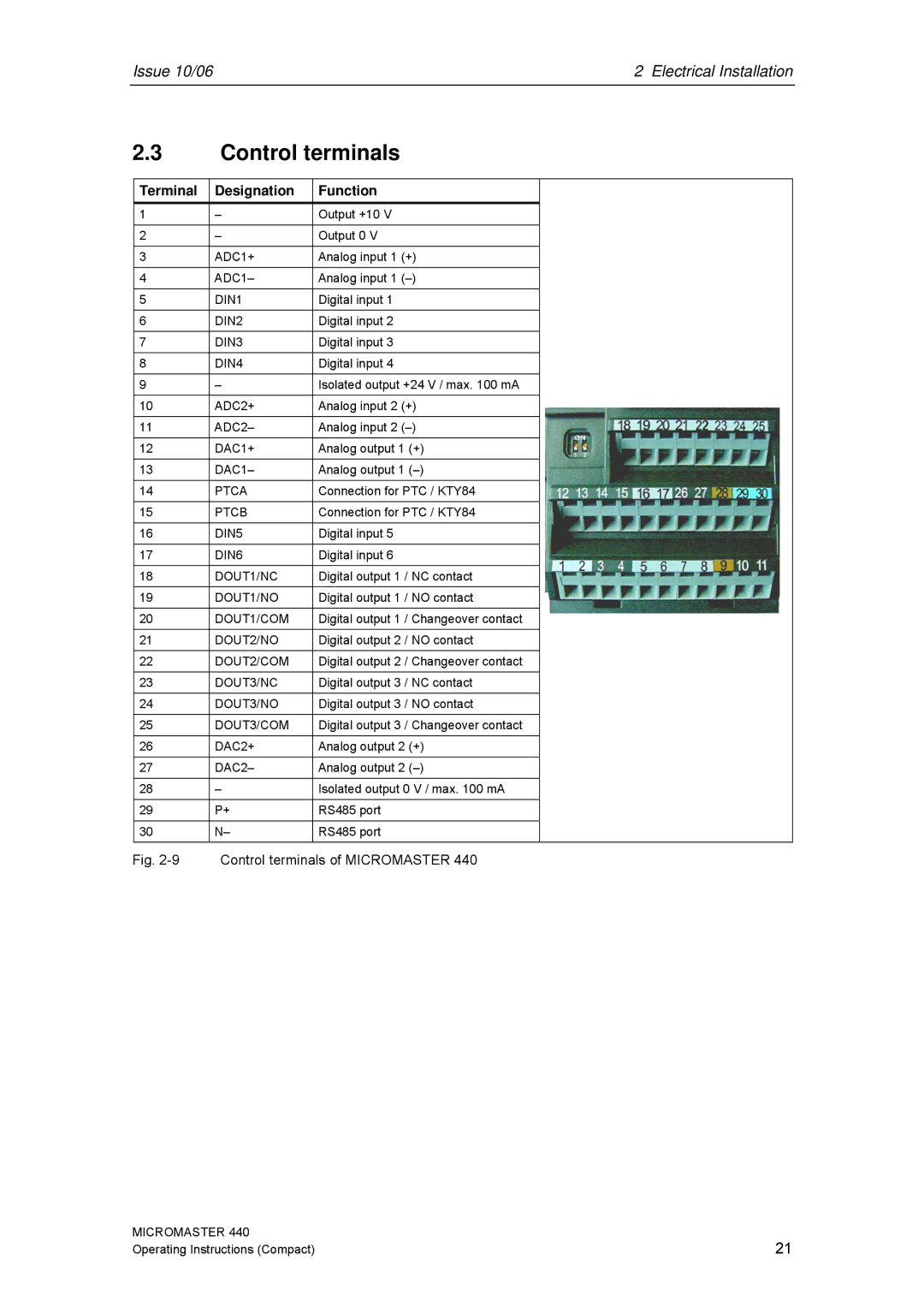
Fig. | Control terminals of MICROMASTER 440 |
| |
MICROMASTER 440 | 21 |
Operating Instructions (Compact) |