DART 200 CDPD Modem User’s Guide | 5 DART Supported Protocols |
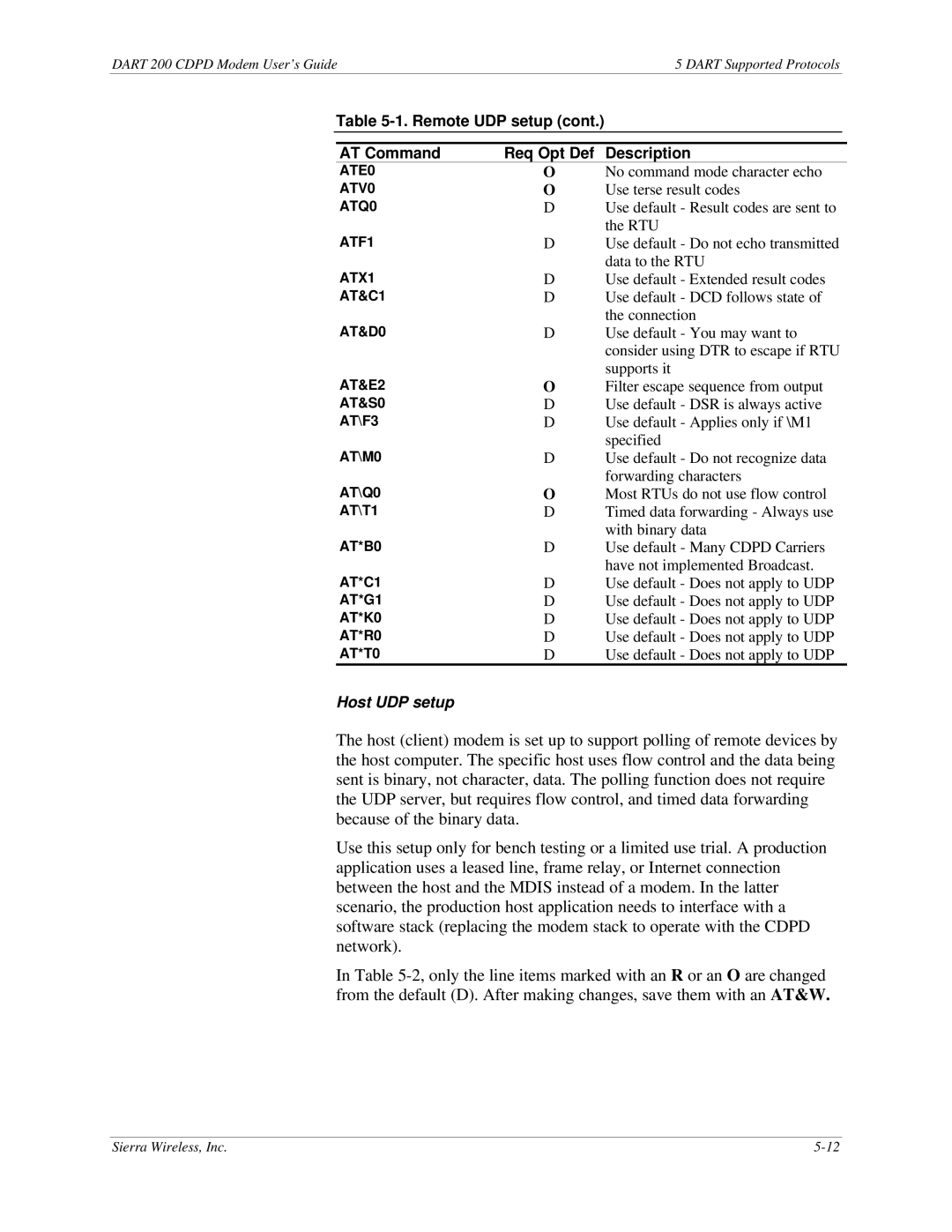
Table 5-1. Remote UDP setup (cont.)
AT Command | Req Opt Def | Description |
ATE0 | O | No command mode character echo |
ATV0 | O | Use terse result codes |
ATQ0 | D | Use default - Result codes are sent to |
ATF1 |
| the RTU |
D | Use default - Do not echo transmitted | |
ATX1 |
| data to the RTU |
D | Use default - Extended result codes | |
AT&C1 | D | Use default - DCD follows state of |
AT&D0 |
| the connection |
D | Use default - You may want to | |
|
| consider using DTR to escape if RTU |
AT&E2 |
| supports it |
O | Filter escape sequence from output | |
AT&S0 | D | Use default - DSR is always active |
AT\F3 | D | Use default - Applies only if \M1 |
AT\M0 |
| specified |
D | Use default - Do not recognize data | |
AT\Q0 |
| forwarding characters |
O | Most RTUs do not use flow control | |
AT\T1 | D | Timed data forwarding - Always use |
AT*B0 |
| with binary data |
D | Use default - Many CDPD Carriers | |
AT*C1 |
| have not implemented Broadcast. |
D | Use default - Does not apply to UDP | |
AT*G1 | D | Use default - Does not apply to UDP |
AT*K0 | D | Use default - Does not apply to UDP |
AT*R0 | D | Use default - Does not apply to UDP |
AT*T0 | D | Use default - Does not apply to UDP |
Host UDP setup
The host (client) modem is set up to support polling of remote devices by the host computer. The specific host uses flow control and the data being sent is binary, not character, data. The polling function does not require the UDP server, but requires flow control, and timed data forwarding because of the binary data.
Use this setup only for bench testing or a limited use trial. A production application uses a leased line, frame relay, or Internet connection between the host and the MDIS instead of a modem. In the latter scenario, the production host application needs to interface with a software stack (replacing the modem stack to operate with the CDPD network).
In Table
Sierra Wireless, Inc. |