DART 200 CDPD Modem User’s Guide | C Charts and Diagrams |
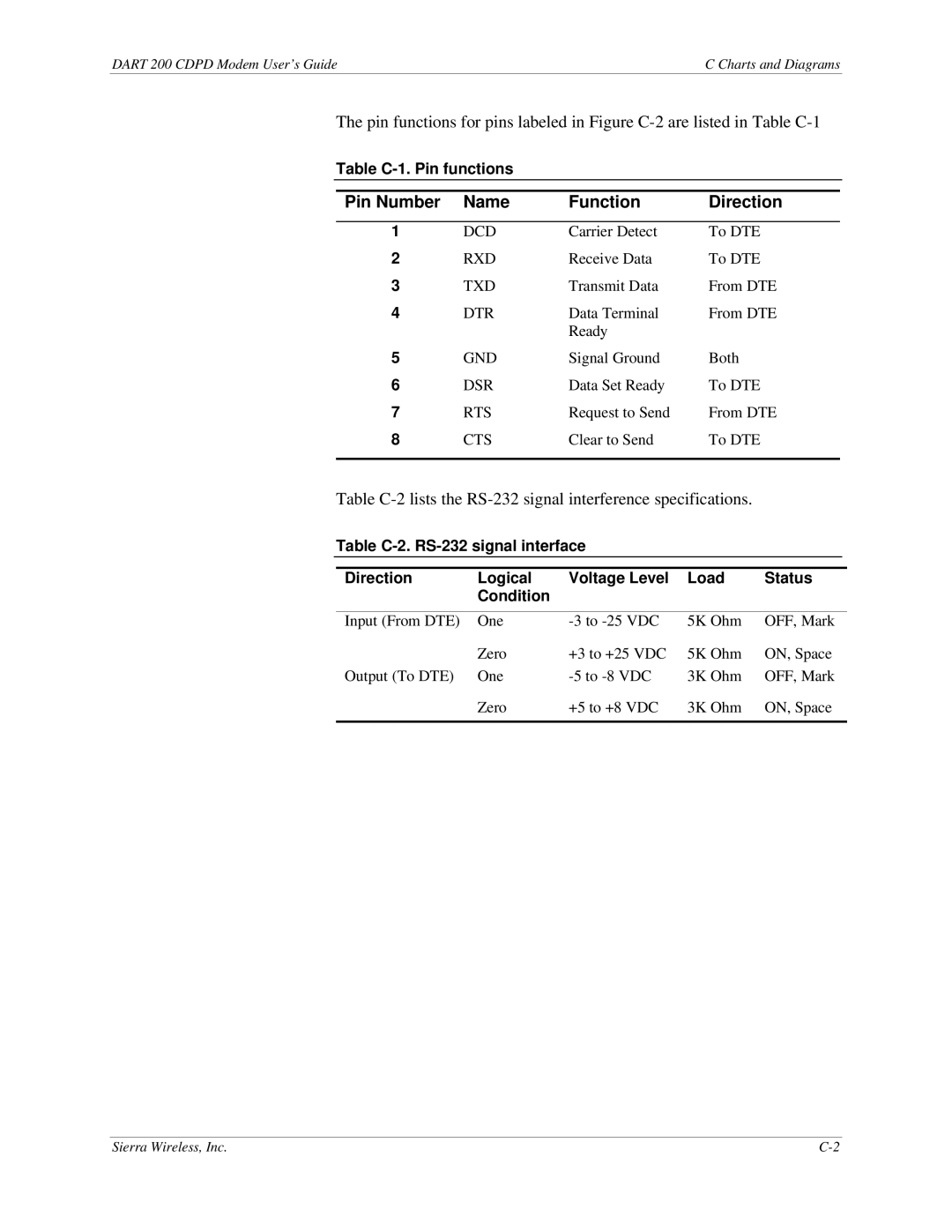
The pin functions for pins labeled in Figure
Table C-1. Pin functions
Pin Number | Name | Function | Direction |
|
|
|
|
1 | DCD | Carrier Detect | To DTE |
2 | RXD | Receive Data | To DTE |
3 | TXD | Transmit Data | From DTE |
4 | DTR | Data Terminal | From DTE |
|
| Ready |
|
5 | GND | Signal Ground | Both |
6 | DSR | Data Set Ready | To DTE |
7 | RTS | Request to Send | From DTE |
8 | CTS | Clear to Send | To DTE |
|
|
|
|
Table
Table
Direction | Logical | Voltage Level | Load | Status |
| Condition |
|
|
|
|
|
|
|
|
Input (From DTE) | One | 5K Ohm | OFF, Mark | |
| Zero | +3 to +25 VDC | 5K Ohm | ON, Space |
Output (To DTE) | One | 3K Ohm | OFF, Mark | |
| Zero | +5 to +8 VDC | 3K Ohm | ON, Space |
|
|
|
|
|
Sierra Wireless, Inc. |
