DART 200 CDPD Modem User’s Guide | 6 Device Attachment |
Figure 6-2. Stand-alone RS-232
DTE
Computer
DCE
Terminal
The problem with this occurs when modems are inserted between the DTE and a remote device with a DCE interface. The modem expects to communicate with a DTE interface. Since this is not the case at the remote end, where the DCE modem is trying to talk to a DCE device, a communications failure results. The solution for this situation is a null modem connector. A typical null modem pin out is shown in Table
Table
Female | Male |
DB9 | DB9 |
1 DCD | 4 |
2 RXD | 3 |
3 TXD | 2 |
4 DTR | 6 and 1 |
5 SGD | 5 |
6 DSR | 4 |
7 RTS | 8 |
8 CTS | 7 |
9 | Open |
The null modem adapter corrects the mismatch between the modem and a terminating device having a DCE interface. The proper location for the null modem is shown in Figure
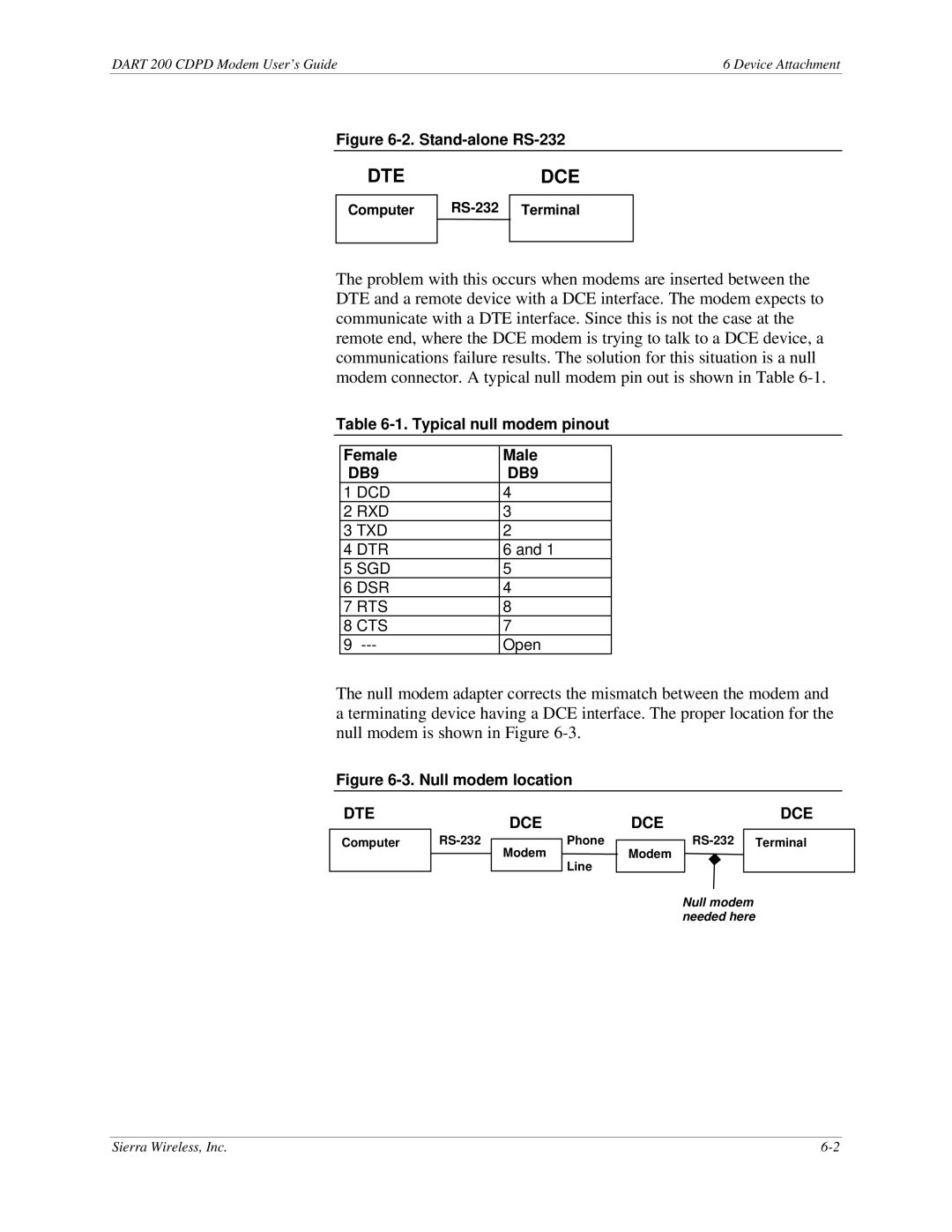
Figure 6-3. Null modem location
DTE
DCE
DCE
DCE
Computer
Modem
Phone
Line
Modem
Null modem needed here
Sierra Wireless, Inc. |