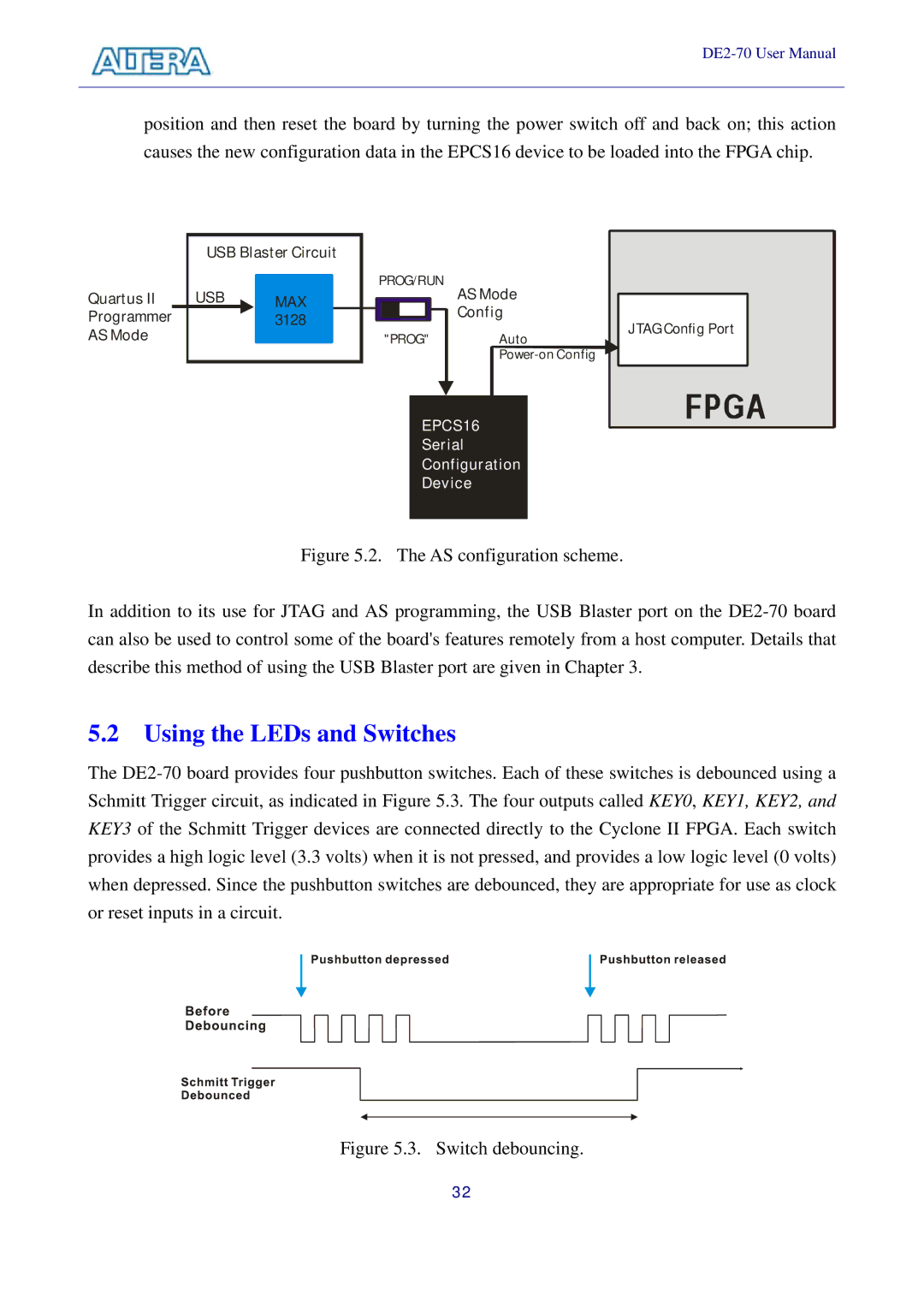
position and then reset the board by turning the power switch off and back on; this action causes the new configuration data in the EPCS16 device to be loaded into the FPGA chip.
USB Blaster Circuit
Quartus II | USB |
|
|
| PROG/RUN | ||
| MAX |
| |||||
|
|
|
|
| |||
|
|
|
|
| |||
|
|
|
|
| |||
Programmer |
|
| 3128 |
|
|
|
|
|
|
|
|
|
| ||
AS Mode |
|
|
|
| "PROG" | ||
|
|
|
| ||||
|
|
|
|
|
|
|
|
AS Mode
Config
Auto | JTAG Config Port |
| |
|
EPCS16
Serial
Configuration
Device
Figure 5.2. The AS configuration scheme.
In addition to its use for JTAG and AS programming, the USB Blaster port on the DE2-70 board can also be used to control some of the board's features remotely from a host computer. Details that describe this method of using the USB Blaster port are given in Chapter 3.
5.2 Using the LEDs and Switches
The
Figure 5.3. Switch debouncing.
32
