VCC5 VCC5 VCC5 VCC5
PS2_KBDAT |
|
| R48 | 120 |
PS2_KBCLK |
|
| R49 | 120 |
PS2_MSDAT |
|
| R174 | 120 |
PS2_MSCLK |
|
| R175 | 120 |
3 | 3 | 3 | 3 |
|
D9 | D10 | D95 | D96 |
BAT54S | BAT54S | BAT54S | BAT54S |
1 | 2 | 1 | 2 | 1 | 2 | 1 | 2 |
| VCC33 |
| VCC33 |
| VCC33 |
| VCC33 |
R46 | R47 | R172 | R173 |
|
2K | 2K | 2K | 2K |
|
|
|
| KBDAT | 1 |
|
|
| MSDAT | 2 |
|
|
| 3 | |
|
|
| KBCLK | 5 |
|
|
| 6 | |
|
| VCC5 | MSCLK | 8 |
|
| BC34 |
| BC35 |
|
| 0.1u |
| |
|
|
|
|
J3
| TOP |
8 | 6 |
53
2 1
9 | PS2 |
10 11 | |
0.1u |
|
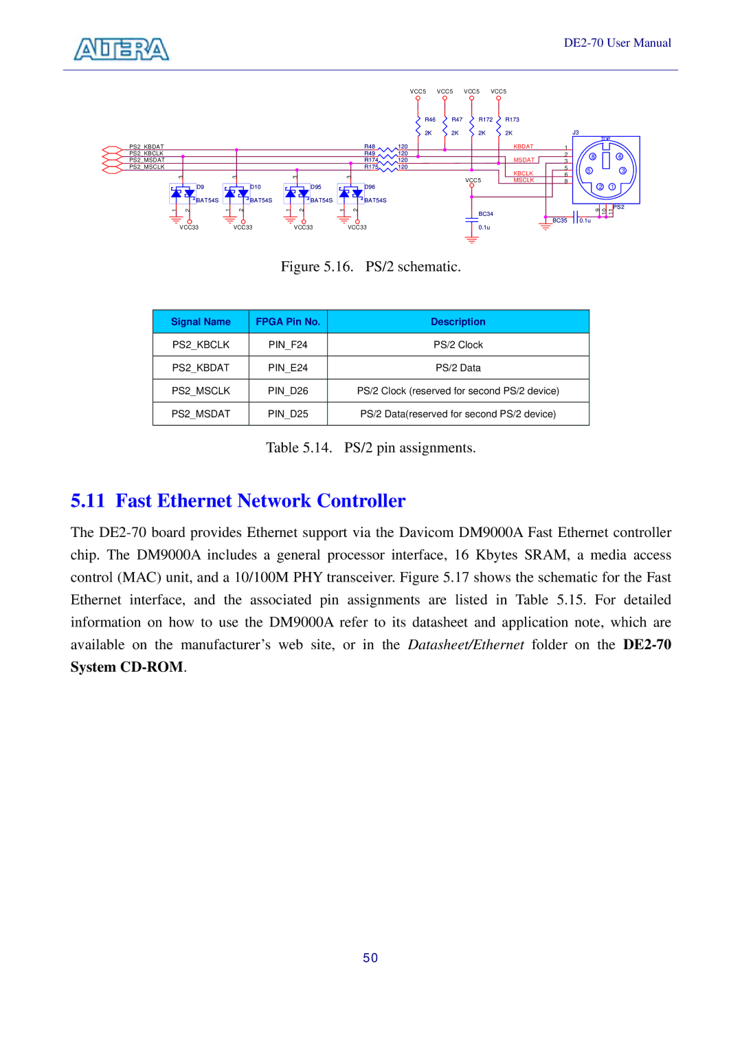
| Figure 5.16. | PS/2 schematic. | |
|
|
|
|
Signal Name | FPGA Pin No. |
| Description |
|
|
|
|
PS2_KBCLK | PIN_F24 |
| PS/2 Clock |
|
|
|
|
PS2_KBDAT | PIN_E24 |
| PS/2 Data |
|
|
|
|
PS2_MSCLK | PIN_D26 |
| PS/2 Clock (reserved for second PS/2 device) |
|
|
|
|
PS2_MSDAT | PIN_D25 |
| PS/2 Data(reserved for second PS/2 device) |
|
|
|
|
Table 5.14. PS/2 pin assignments.
5.11 Fast Ethernet Network Controller
The
50